Noise in Amateur Radio Receiving Systems David Conn


- Slides: 34

Noise in Amateur Radio Receiving Systems David Conn VE 3 KL Credit: Nasa and Jack Newton http: //antwrp. gsfc. nasa. gov/apod/ap 040726. html 5/25/2021 David Conn VE 3 KL QCWA Oct. 2004 K = 1. 38*(10 -23) 1

Acknowledgments QCWA Travelers/Committee Croft Taylor Gus Holtz Doug Leach Clare Fowler Bert Barry 5/25/2021 VE 3 CT VE 3 VK VE 3 XK VE 3 NPC VE 3 QAA David Conn VE 3 KL QCWA Oct. 2004 2

Introduction ► A talk about noise levels in amateur radio systems: SSB, CW, PSK 31, EME… ► Noise Types: Thermal, Shot, Flicker atmospheric, man-made…… ► Measured with an ideal S meter Signal Levels 5/25/2021 David Conn VE 3 KL QCWA Oct. 2004 3

Signal Levels 326 d. Bm 124 d. Bm 50 d. Bm -73 d. Bm SUN Niagara Falls Power Generation 100 Watt Radio Transmitter S 9 at receiver front end -144 d. Bm Resistor: room temperature (I KHz BW) -162 d. Bm Sky background noise (1 KHz BW) 5/25/2021 David Conn VE 3 KL QCWA Oct. 2004 4

Noise Types ► Thermal: ► Shot: Moving electrons in conductors : KTB DC current flow in semiconductors ► Flicker or 1/f noise: like earth quakes in devices ► Man-made : Can propagate via ionospheric skip ► Atmospheric/ionospheric/sky……. . 5/25/2021 David Conn VE 3 KL QCWA Oct. 2004 5

Thermal Noise Power = KTB -144 d. Bm (290 K, 1 KHz BW) Amplifier G=1 Noiseless Bandpass Filter B = bandwidth Power = KTo. B Watts Resistor at Temperature To 5/25/2021 David Conn VE 3 KL QCWA Oct. 2004 6

Noise Figure, F Effective Temperature Te Amplifier G=1 Noisy Bandpass Filter B = bandwidth Power = FKTo. B = K(To +Te)B Resistor at Temperature To 5/25/2021 David Conn VE 3 KL QCWA Oct. 2004 7

Noise Figure Or Noise Temperature Can use either to measure receivers F = 1 +Te/To Moon Temperature 5/25/2021 David Conn VE 3 KL QCWA Oct. 2004 8

Noise Temperature Moon, Sky, Ground Antenna Ideal Receiver Thermal Radiation Tm Po = KTm. B Moon 5/25/2021 David Conn VE 3 KL QCWA Oct. 2004 9

Thermal Noise …Moon Credit: http: //www. spacelink. msfc. nasa. gov/Instructional. Mate rials http: //www. vhfdx. net/w 5 luu. html Moon Temperature 510 K Oct 17, 2004: -141 d. Bm (1 KHz) Varies with time: 510 K is poor for EME Communications 5/25/2021 David Conn VE 3 KL QCWA Oct. 2004 10

Examples of Noise Levels Application Noise Figure Te Power (d. Bm) (1 KHz) Microwave 3 d. B 290 -144 d. Bm HF 53 d. B 57, 000 -121 d. Bm…. S 1 Low Noise Applications 0. 7 d. B 50 K -151 d. Bm 5/25/2021 David Conn VE 3 KL QCWA Oct. 2004 11

HF Man-Made Noise Signal + Noise Antenna Balun Power line Noise Tx/Rx Coiled coax Ground 5/25/2021 David Conn VE 3 KL QCWA Oct. 2004 12

The S Meter ► Our Basic Power Meter ► Measures Power at the receiver input ► Usually not well calibrated 5/25/2021 David Conn VE 3 KL QCWA Oct. 2004 13

Definition of Terms ► S is the reading on an S meter. ► Field strength (Volts/m) is a measure of the electric field strength at the receiver ► Aeff is the effective area of a lossless antenna, related to directivity 5/25/2021 David Conn VE 3 KL QCWA Oct. 2004 14

The Radio Model: Signal and Noise Ionosphere Isotropic Tx Loss Doppler: limits PSK 31 Amplitude distortion R Rx Power, Noise S/N S Meter Bandwidth Power = 1. 0 W Transmitted 5/25/2021 Short Dipole ├ סּ Г David Conn VE 3 KL QCWA Oct. 2004 15

Effective Area of a Short Dipole ► Area not a function of dipole length ► For a 20 m dipole Aeff = 48 square metres ► Area depends only on λ 2 5/25/2021 David Conn VE 3 KL QCWA Oct. 2004 16

Received Signal Power Transmitted = 1. 0 W 5/25/2021 David Conn VE 3 KL QCWA Oct. 2004 17

Man-Made Noise Analysis ► Data from ITU-R P. 372 -7 Report ► Man-made noise relative to thermal noise. Not dependent on the bandwidth ► Translate to S units for our use. 5/25/2021 David Conn VE 3 KL QCWA Oct. 2004 18

ITU Noise Data (Field Strength) 5/25/2021 David Conn VE 3 KL QCWA Oct. 2004 19

Noise in SSB : BW = 2700 Hz 5/25/2021 David Conn VE 3 KL QCWA Oct. 2004 20

Noise In CW : BW = 500 Hz 5/25/2021 David Conn VE 3 KL QCWA Oct. 2004 21

The Shannon Hartley Limit CW Morse Code: P/N = 3 S units, B= 100 Hz Then: C = 1438 words per minute P is the signal power N is the noise power B is the receiver bandwidth 5/25/2021 David Conn VE 3 KL QCWA Oct. 2004 22

Noise in PSK 31 BW = 62. 5 Hz 5/25/2021 David Conn VE 3 KL QCWA Oct. 2004 23

Solutions to the Noise Problem ► Keep antennas away from houses and power lines. ► Use a Balun at the antenna ► Use shielded coax cables for best results. ► Use a grounding system to suppress noise that comes from currents flowing up to the antenna on the outside of the coax. ► Bury the coax cable: moisture problem? 5/25/2021 David Conn VE 3 KL QCWA Oct. 2004 24

Filter External Cable Noise: Use a PI network Signal + Noise Antenna Balun Power line Noise Tx/Rx Coiled coax Ground 5/25/2021 David Conn VE 3 KL QCWA Oct. 2004 25

Summary ► Man-made ► EME Noise Dominates at MF/HF requires low temp receivers ► No need for very low noise receivers at HF ► HF receivers need high dynamic range 5/25/2021 David Conn VE 3 KL QCWA Oct. 2004 26

Thanks for Attending 73 David 5/25/2021 David Conn VE 3 KL QCWA Oct. 2004 27

Following are back up slides 5/25/2021 David Conn VE 3 KL QCWA Oct. 2004 28

Effective Area: Parabolic Dish A 2 metre parabolic dish Freq = 1296 MHz Wavelength = 23. 8 cm Physical area = 3. 14 square metres Aeff = 1. 73 square metres 5/25/2021 David Conn VE 3 KL QCWA Oct. 2004 29

The Shannon Hartley Limit CW Morse Code: P/N = 3 S units IF C = 20 words per minute Then: B = 1. 4 Hz 5/25/2021 David Conn VE 3 KL QCWA Oct. 2004 30

Effective Area 5/25/2021 David Conn VE 3 KL QCWA Oct. 2004 31

Effective Area: Yagi A three element 10 m Yagi, free space Gain = 8. 4 d. B Aeff = 55 square Metres 5/25/2021 David Conn VE 3 KL QCWA Oct. 2004 32

Summary ► Main output: S meter graphs for SSB ► You can use these graphs to evaluate your own location ► We have a long way to go to get close to the Shannon - Hartley limit ► The issue of noise pollution needs our attention and careful measurements 5/25/2021 David Conn VE 3 KL QCWA Oct. 2004 33

Where to Get More Information ► RAC Web site: look there first ► ARRL Web site ► Details in my web site as it develops ► Fields and Waves in Communication Electronics: Ramo, Whinnery, Van Duzer ; John Wiley, third edition, 1994, ISBN 0 -0471 -58551 -3 5/25/2021 David Conn VE 3 KL QCWA Oct. 2004 34
 Ham radio remote control
 Ham radio tonga
 Boulder amateur radio club
 Ubiquiti link calculator download
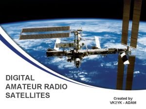
 Amateur radio digital communications
 Chelmsford amateur radio society
 Chelmsford amateur radio society
 Chelmsford amateur radio society
 Bbhn
Bbhn Quantizing noise (quantization noise):
 Osce data interpretation
 Conn's syndrome
 Conn vs addison
 Preparedstatement pstmt = conn.preparestatement(sql)
 Diaporama a la conn.fr
 Conn plus
 Principal cells
 Trunking vs conventional radio system
 Where may ssb phone be used in amateur bands above 50 mhz?
 Random amateur
 Club lust production
 Katrina amateur
 M.vk amateur
 Isanyoneup
 Amateur sp
 Amateur sdx
 Japanese amateur jc
 Student teacher amateur
 Insemination amateur
 Telescopio amateur
 New york state amateur hockey association
 Signalink usb occasion
 Receiving table/area
 Raw material receiving process
 Facegmail
