Electronic Noise Noise phenomena Device noise models Representation


 as a voltage source across")


, its autocorrelation is defined as: If n(t)")
 is: For real")

 PSDx(f)")
 H(s) y(t)")
 could take")


 Get small-signal model 2) Set all inputs = 0 (linear superposition)")
/go. T VDD go. T = 1/RL +")


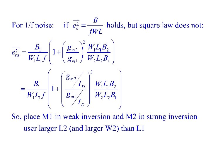
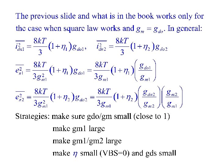
 L 2 >>L 1 2) en 1 small")


- Slides: 50
Electronic Noise • Noise phenomena • Device noise models • Representation of noise (2 -ports): – – – Motivation Output spectral density Input equivalent spectral density Noise figure Sampling noise (“k. T/C noise”) • SNR versus Bits • Noise versus Power Dissipation – Dynamic range – Minimum detectable signal
Noise in Devices and Circuits • Noise is any unwanted excitation of a circuit, any input that is not an information-bearing signal. • External noise: Unintended coupling with other parts of the physical world; in principle, can be virtually eliminated by careful design. • Intrinsic noise: Unpredictable microscopic events inherent in the device/circuit; can be reduced, but never eliminated. • Noise is especially important to consider when designing low-power systems because the signal levels (typically voltages or currents) are small.
Noise vs random process variations • random process variations – Variations from one device to another – For any device, it is fixed after fabrication • Noise – Unpredictable variations during operation – Unknown after fabrication – Remains unknown after measurement during operation – May change with environment
Time domain description of noise
What is signal and what is noise?
Signal and noise power:
Physical interpretation If we apply a signal (or noise) as a voltage source across a one Ohm resistor, the power delivered by the source is equal to the signal power. Signal power can be viewed as a measure of normalized power
Signal to noise ratio SNR = 0 d. B when signal power = noise power Absolute noise level in d. B: w. r. t. 1 m. W of signal power
SNR in bits • A sine wave with amplitude 1 has power = 1/2. • Quantize it into N=2 n equal levels between -1 and 1 (with step size = 2/2 n) • Quantization error uniformly distributed between +– 1/2 n • Noise (quantization error) power =1/3 (1/2 n)2 • Signal to noise ratio = 1/2 ÷ 1/3 (1/2 n)2 =1. 5(2 n)2 = 1. 76 + 6. 02 n d. B or n bits
-1<= C <=+1 C=0: n 1 and n 2 uncorrelated C=1: perfectly correlated C=-1: n 1 and –n 2 perfectly correlated
Adding uncorrelated noises Adding correlated noises
For independent noises
Autocorrelation of a random process Given n(t), its autocorrelation is defined as: If n(t) (wide sense)stationary, then:
Power spectral density of noise The power spectral density of n(t) is: For real noise,
Ergodicity and time average of noise A random process is Ergodic if its ensemble statistics can be computed from time samples.
Interpretation of PSD Pxf 1 = PSDx(f 1) PSDx(f)
Filtering of noise x(t) H(s) y(t)
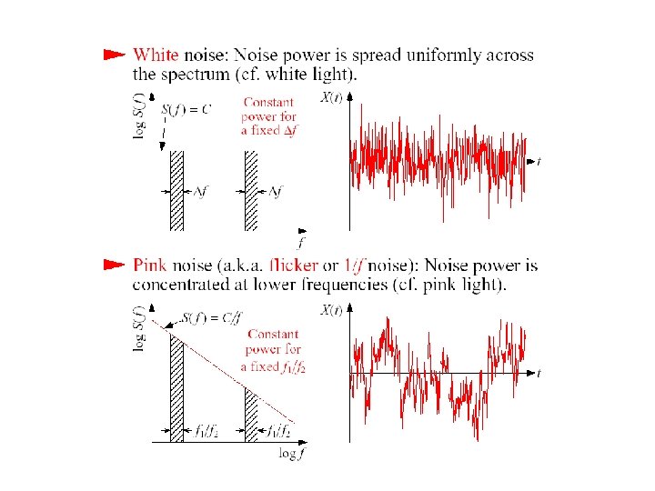
Three ways to view noise • For a given t, – n(t) could take various, random values – These values have a distribution pdf, e. g. , uniform in [N 1, N 2], or Gaussian N(m, s), or just 0/1. – If a large number of these values taken, can use histogram to obtain approximate pdf • Take one value of n(t) at each t, plot n(t) ~ t we get n(t)’s time waveform – Can look at statistics of n(t) over t • Translate into frequency domain PSD – White: spectrum is flat ~ f – 1/f noise: spectrum has 1/f shape near low frequency
Types of “Noise” • “man made” – Interference – Supply noise –… – Use shielding, careful layout, isolation, … • “intrinsic” noise – Associated with current conduction – “fundamental” –thermal noise – “manufacturing process related” – flicker noise
Thermal Noise • Due to thermal excitation of charge carriers in a conductor. It has a white spectral density and is proportional to absolute temperature, not dependent on bias current. • Random fluctuations of v(t) or i(t) • Independent of current flow • Characterization: – Zero mean, Gaussian pdf – Power spectral density constant or “white” up to about 80 THz
Thermal noise dominant in resisters Example: R = 1 kΩ, B = 1 MHz, 4µV rms or 4 n. A rms
Noise in Diodes Shot noise dominant – DC current is not continuous and smooth but instead is a result of pulses of current caused by the individual flow of carriers. It depends on bias, can be modeled as a white noise source and typically larger than thermal noise. − Zero mean – Gaussian pdf – Power spectral density flat – Proportional to current – Dependent on temperature
Example: ID= 1 m. A, B = 1 MHz, 17 n. A rms
MOS Noise Model
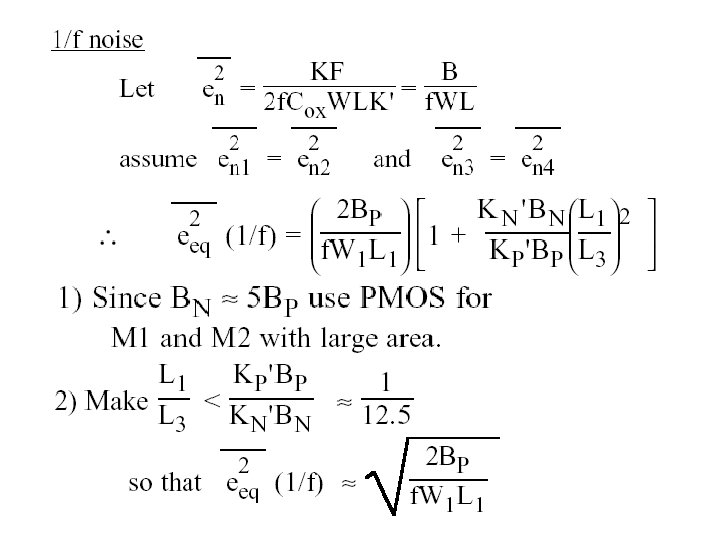
Flicker noise As a gate voltage, 1/Gate-Cap – Kf, NMOS 6 times larger than Kf, PMOS – Strongly process dependent – When referred to as drain current noise, it is inversely proportional to L 2 Nominal values for AF and EF are both 1.
Channel thermal noise current A modified model of noise current Qinv
BJT Noise
Sampling Noise • Commonly called “k. T/C” noise • Applications: ADC, SC circuits, … R von C Used:
Noise Calculations 1) Get small-signal model 2) Set all inputs = 0 (linear superposition) 3) Pick an output variable vo or io 4) For each noise source vx, or ix Calculate TF Hx(s) from input x to output 5) Total noise at output is 6) Input Referred Noise: Fictitious noise source at input:
Example: CS Amplifier Von=(in. RL +in. MOS)/go. T VDD go. T = 1/RL + s. CL RL M 1 CL
wo=1/RLCL
Some integrals
HW Equivalently, we can model a real resistor with an ideal resistor in parallel with a current noise source. What rms value should the current source have? Show that when two resistors are connected in series, we can model them as ideal series resistors in series with a single noise voltage source. What’s the rms value of the voltage source? Show that two parallel resistors can be modeled as two ideal parallel resistors in parallel with a single noise current source. What’s the rms value of the current source?
HW In the previous example, if the transistor is in triode, how would the solution change? HW If we include the flicker noise source, how would that affect the computation? What do you suggest we should modify? HW In the example, if RL is replaced by a PMOS transistor in saturation, how would the solution change? Assume appropriate bias levels.
NOISE IN MOS INVERTERS
To minimize: 1) L 2 >>L 1 2) en 1 small
For thermal noise
NOISE Model
Input equivalent noise source
• Total output noise current is found as, • Let • Then
How does this affect Av 4 and go?
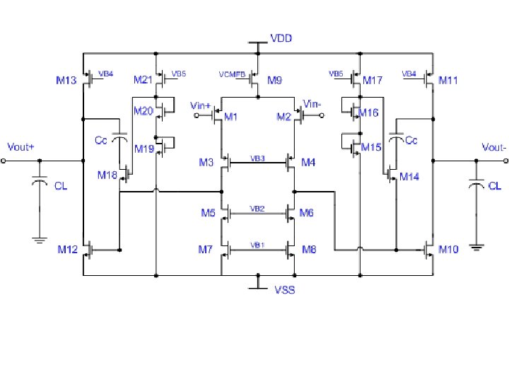
VDD IN- Did noise computation in class for this amp IN+ CC Vo-
VDD Vb. Pc IN- IN+ Vb. Nc CC Vo