Nanoscale Cr 4 Doped Olivine Crystallites in GlassCeramics


- Slides: 19
Nanoscale Cr 4+ – Doped Olivine Crystallites in Glass-Ceramics for NIR Optical Amplifiers and Lasers By: Fayette Colon Mentor: Mikhail Sharonov Assistant Mentor: Thandar Myint
Abstract • The purpose of this experiment is to fabricate Cr 4+ ion doped laser crystals and characterize glass ceramics containing nanoscale crystallites of Cr 4 + - doped laser materials such as Cr 4+ : Mg 2 Si. O 4 and Cr 4+ : Ca 2 Ge. O 4. The glass ceramic is important because it can be used in several applications such as the fiber amplifier, fiber laser and for other medical purposes.
Objectives 1. Material preparation • To uncover a proper host for the Cr 4+ ion through the research of the Li. In. Si. O 4 and Ca. Si. O 4 systems. 1. Optical characterization of materials • To compare a glass ceramic doped with nanocrystallite Cr 4+ ions and bulk laser crystals, such as Cr 4+ : Mg 2 Si. O 4 or Cr 4+ : Ca 2 Ge. O 4 to observe whether it has the same characteristics as the individual bulk crystals.
What is a laser? • It is an acronym for Light Amplification by the Stimulated Emission of Radiation § A laser produces near- monochromatic light § Has a single precise wavelength or hue § The light is coherent § The photons emitted have a definite phase relationship § Laser beams are collimated § They are narrow and concentrated
Electronics to Support Synchronization Between the Lasers The circuit used two non-inverting operational amplifiers In a non-inverting input the output polarity is the same as the input polarity
Laser System: Diode-pumped Nd: YAG laser: 532 nm, 8 ps, 82 MHz, 1. 85 W Dye Laser with mode-locking: 610 nm, 1 ps, 82 MHz, 170 mw Synchronization Q-switch pulsed Nd: YAG laser: 532 nm, ~5 ns, 30 Hz, ~330 m. J Thandar Myint Pulsed Dye Amplifier: 610 nm, ~1 ps, 30 Hz, ~5 m. J/pulse
Importance of the Circuit • The circuit serves as a component to the laser system • It is designed to aid in synchronizing the pump and the signal pulses in order to reach the laser amplifier at the same time.
Raman Measurement
Spectrometer/ Detector • A Spectrometer is an optical instrument which measures the properties of light over a portion of the electromagnetic spectrum. The measured variable is often the intensity and the independent variable is the wavelength. • A Detector is a device which is designed to detect the presence of something as well as to emit a signal in response.
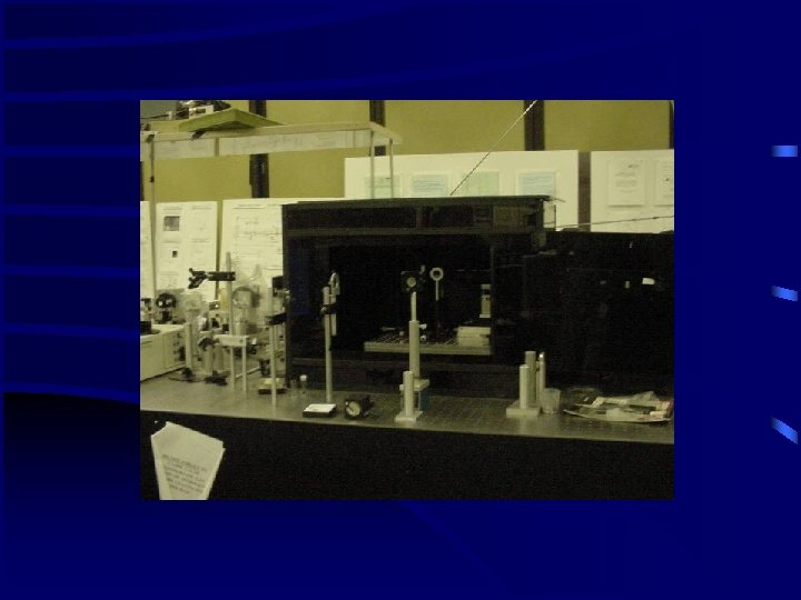
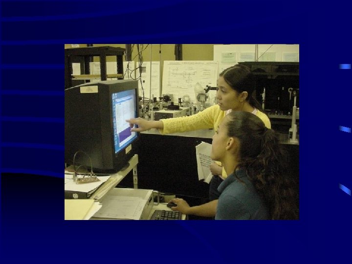
Experimental Set Up F. Colon
Experimental Information • A He. Ne laser was used; it generates a 632. 3 nm laser line and its power is about 1 m. W. – The light passed through a filter (which selectively transmits certain portion of light) then reflected onto a mirror at 45 degrees – The light beam then reflected onto a second mirror and through a second filter – The laser was again reflected onto a mirror through a lens (which is 12 cm from the crystal) to be reflected on a fourth mirror and into the glass ceramic crystal – The light then scattered and was collected by a Camera Lens following which it went into the Spectrometer. – The Camera Lens must be finely adjusted to receive good focusing
Results
Further Results
Analysis of the Results • The graph shows the light intensity versus wavelength of He. Ne laser. • The maximum power of the He. Ne laser is located at 632. 8 nm. • The shape of the image is well-known Gaussian shape, which means that the intensity is concentrated in the center and gradually decreases at the tails. • Although this was merely a test trial for the experiment its importance lies with the layout of the experimental instruments.
Further Work • The Research team will use the results of the test trial to create a more efficient layout for the experiment. • Following which the high intensity laser will be used for the actual experiment along with the circuit created • Completion of this experiment is important because the data received will show the characteristics of the glass ceramic; obtaining this knowledge will lead to realize the proposed application such as optical amplifiers.
Acknowledgements • Mentors: Mikhail Sharnovo and Thandar Myint • NASA SHARP • NASA COSI and Do. D NPC Summer Program • City College of New York • CREST –CMMS • NYC-MTA
References • “Characteristics of Laser Light” – http: //en. wikipedia. org • “What is a Laser? ” – http: //en. wikipedia. org • “Detector” – http: //en. wikipedia. org