Magnetic Field due to a Current Carrying Wire


- Slides: 24
Magnetic Field due to a Current. Carrying Wire Biot-Savart Law AP Physics C Mrs. Coyle Hans Christian Oersted, 1820
• Magnetic fields are caused by currents. • Hans Christian Oersted in 1820’s showed that a current carrying wire deflects a compass. Current in the Wire No Current in the Wire
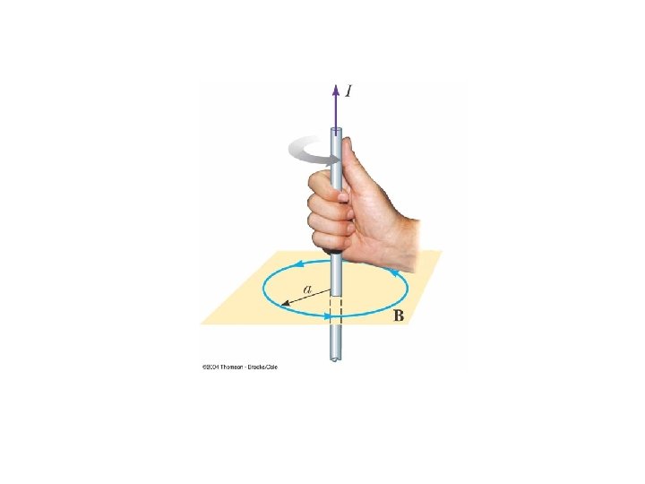
Right Hand Curl Rule
Magnetic Fields of Long Current-Carrying Wires B = mo I 2 p r I = current through the wire (Amps) r = distance from the wire (m) mo = permeability of free space = 4 p x 10 -7 T m / A B = magnetic field strength (Tesla) I
Magnetic Field of a Current Carrying Wire • http: //www. walterfendt. de/ph 14 e/mfwire. htm
What if the current-carrying wire is not straight? Use the Biot-Savart Law: Assume a small segment of wire ds causing a field d. B: Note: d. B is perpendicular to ds and r
Biot-Savart Law allows us to calculate the Magnetic Field Vector • To find the total field, sum up the contributions from all the current elements I ds • The integral is over the entire current distribution
Note on Biot-Savart Law • The law is also valid for a current consisting of charges flowing through space • ds represents the length of a small segment of space in which the charges flow. • Example: electron beam in a TV set
Comparison of Magnetic to Electric Field Magnetic Field Electric Field • • B proportional to r 2 Vector Perpendicular to FB , ds, r Magnetic field lines have no beginning and no end; they form continuous circles • Biot-Savart Law • Ampere’s Law (where there is symmetry E proportional to r 2 Vector Same direction as FE Electric field lines begin on positive charges and end on negative charges • Coulomb’s Law • Gauss’s Law (where there is symmetry)
Derivation of B for a Long, Straight Current-Carrying Wire Integrating over all the current elements gives
If the conductor is an infinitely long, straight wire, q 1 = 0 and q 2 = p • The field becomes: a
B for a Curved Wire Segment • Find the field at point O due to the wire segment A’ACC’: B=0 due to AA’ and CC’ Due to the circular arc: • q=s/R, will be in radians
B at the Center of a Circular Loop of Wire • Consider the previous result, with q = 2 p
Note • The overall shape of the magnetic field of the circular loop is similar to the magnetic field of a bar magnet.
B along the axis of a Circular Current Loop • Find B at point P If x=0, B same as at center of a loop
If x is at a very large distance away from the loop. x>>R:
Magnetic Force Between Two Parallel Conductors • The field B 2 due to the current in wire 2 exerts a force on wire 1 of F 1 = I 1 ℓ B 2
Magnetic Field at Center of a Solenoid B = mo NI L N: Number of turns L: Length n=N/L ------------L--------
Direction of Force Between Two Parallel Conductors If the currents are in the: –same direction the wires attract each other. –opposite directions the wires repel each other.
Magnetic Force Between Two Parallel Conductors, FB • Force per unit length:
Definition of the Ampere • When the magnitude of the force per unit length between two long parallel wires that carry identical currents and are separated by 1 m is 2 x 10 -7 N/m, the current in each wire is defined to be 1 A
Definition of the Coulomb • The SI unit of charge, the coulomb, is defined in terms of the ampere • When a conductor carries a steady current of 1 A, the quantity of charge that flows through a cross section of the conductor in 1 s is 1 C
Biot-Savart Law: Field produced by current carrying wires – Distance a from long straight wire – Centre of a wire loop radius R – Centre of a tight Wire Coil with N turns • Force between two wires