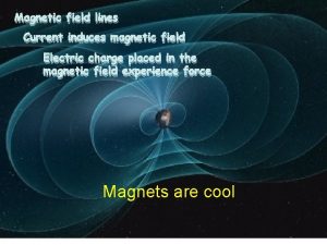
MAGNETIC EFFECT OF ELECTRIC CURRENT 1 Magnetic Effect


- Slides: 24

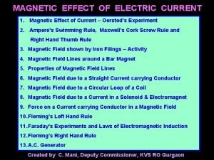
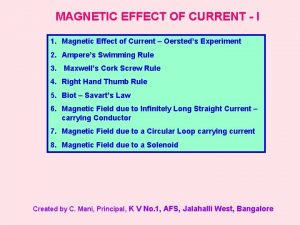
MAGNETIC EFFECT OF ELECTRIC CURRENT 1. Magnetic Effect of Current – Oersted’s Experiment 2. Ampere’s Swimming Rule, Maxwell’s Cork Screw Rule and Right Hand Thumb Rule 3. Magnetic Field shown by Iron Filings – Activity 4. Magnetic Field Lines around a Bar Magnet 5. Properties of Magnetic Field Lines 6. Magnetic Field due to a Straight Current carrying Conductor 7. Magnetic Field due to a Circular Loop of a Coil 8. Magnetic Field due to a Current in a Solenoid & Electromagnet 9. Force on a Current carrying Conductor in a Magnetic Field 10. Fleming’s Left Hand Rule 11. Faraday’s Experiments and Laws of Electromagnetic Induction 12. Fleming’s Right Hand Rule 13. A. C. Generator Created by C. Mani, Deputy Commissioner, KVS RO Gurgaon

Magnetic Effect of Current: An electric current (i. e. flow of electric charge) produces magnetic effect in the space around the conductor called strength of Magnetic field or simply Magnetic field. Oersted’s Experiment: (Hans Christian Oersted (1777 -1851) When current was allowed to flow through a wire placed parallel to the axis of a magnetic needle kept directly below the wire, the needle was found to deflect from its normal position. N E I K N E K I When current was reversed through the wire, the needle was found to deflect in the opposite direction to the earlier case.

Rules to determine the direction of magnetic field: Ampere’s Swimming Rule or SNOW Rule: W N N S I Imagining a man who swims in the direction of current from south to north facing a magnetic needle kept under him such that current enters his feet then the North pole of the needle will deflect towards his left hand, i. e. towards West.

Maxwell’s Cork Screw Rule or Right Hand Screw Rule: I I B B If the forward motion of an imaginary right handed screw is in the direction of the current through a linear conductor, then the direction of rotation of the screw gives the direction of the magnetic lines of force around the conductor.

Right Hand Thumb Rule or Curl Rule: I B If a current carrying conductor is imagined to be held in the right hand such that the thumb points in the direction of the current, then the tips of the fingers encircling the conductor will give the direction of the magnetic lines of force.

Magnetic Field - Activity Iron filings alligned along. Iron withfilings magnetic sprinkled field lines S N Courtesy: Pattern of iron filings from Internet

Magnetic Field Lines around a Magnetic Dipole or Bar Magnet S N B

Properties of Magnetic Field Lines: 1. Magnetic field lines, by convention, emerge from North pole and enter at the South pole. 2. Inside the magnet, the field line is from South to North pole. 3. Thus, the magnetic field lines are closed curves. 4. No two magnetic field lines ever cross each other. If they did, it would mean that at the point of intersection, two magnetic fields would exist and the compass needle would point to two directions, which is not possible. 5. The relative strength of the magnetic field is shown by the degree of closeness of the field lines. The crowded lines indicate stronger magnetic field and the sparse lines indicate weaker field. 6. Magnetic field is a vector quantity having both magnitude and direction.

MAGNETIC FIELD DUE TO A STRAIGHT CURRENT CARRYING CONDUCTOR I I B B E I I Magnetic Field Lines K K E

Magnetic Field Lines due to a straight current indicated by iron filings Courtesy: Internet

Different views of direction of current and magnetic field due to circular loop of a coil I I I B B I E I I K I B I I Eye

Magnetic Field due to a Current in a Solenoid B I I E K TIP: When we look at any end of the coil carrying current, if the current is in anti-clockwise direction then that end of coil behaves like North Pole and if the current is in clockwise direction then that end of the coil behaves like South Pole.

Electromagnet I I E K

Force on a Current Carrying Conductor in a Magnetic Field N I S E K I

Fleming’s Left Hand Rule: Force (F) Magnetic Field (B) Electric Current (I) If the central finger, fore finger and thumb of left hand are stretched mutually perpendicular to each other and the central finger points to current, fore finger points to magnetic field, then thumb points in the direction of motion (force) on the current carrying conductor. TIP: Remember the phrase ‘e m f’ to represent electric current, magnetic field and force in anticlockwise direction of the fingers of left hand.

Faraday’s Experiment - 1: S N N N S G N G S S S G S N N G

S N N S G Magnetic flux linked with the coil changes relative to the positions of the coil and the magnet due to the magnetic lines of force cutting at different angles at the same cross sectional area of the coil.

Observe: i) the relative motion between the coil and the magnet ii) the induced polarities of magnetism in the coil iii) the direction of current through the galvanometer and hence the deflection in the galvanometer iv) that the induced current (e. m. f) is available only as long as there is relative motion between the coil and the magnet Note: i) coil can be moved by fixing the magnet ii) both the coil and magnet can be moved (towards each other or away from each other) i. e. there must be a relative velocity between them iii) magnetic flux linked with the coil changes relative to the positions of the coil and the magnet iv) current and hence the deflection is large if the relative velocity between the coil and the magnet and hence the rate of change of flux across the coil is more

Faraday’s Experiment - 2: N S S P N G S P E During this period, changing current induces changing magnetic flux across the primary coil. S K E N N S S K G When the primary circuit is closed current grows from zero to maximum value. This changing magnetic flux is linked across the secondary coil and induces e. m. f (current) in the secondary coil. Induced e. m. f (current) and hence deflection in galvanometer lasts only as long as the current in the primary coil and hence the magnetic flux in the secondary coil change.

When the primary circuit is open current decreases from maximum value to zero. During this period changing current induces changing magnetic flux across the primary coil. This changing magnetic flux is linked across the secondary coil and induces current (e. m. f) in the secondary coil. However, note that the direction of current in the secondary coil is reversed and hence the deflection in the galvanometer is opposite to the previous case. Faraday’s Laws of Electromagnetic Induction: I Law: Whenever there is a change in the magnetic flux linked with a circuit, an emf and hence a current is induced in the circuit. However, it lasts only so long as the magnetic flux is changing. II Law: The magnitude of the induced emf is directly proportional to the rate of change of magnetic flux linked with a circuit. E α dΦ / dt E = k dΦ / dt E = (Φ 2 – Φ 1) / t (where k is a constant and units are chosen such that k = 1)

Fleming’s Right Hand Rule: Magnetic Field (B) Force (F) Electric Current (I) If the central finger, fore finger and thumb of right hand are stretched mutually perpendicular to each other and the fore finger points to magnetic field, thumb points in the direction of motion (force), then central finger points to the direction of induced current in the conductor.

A. C. Generator Q R S S R Q N N S P S R 1 B 1 R 2 P R 1 B 1 R 2 B 2 Load A. C. Generator or A. C. Dynamo or Alternator is a device which converts mechanical energy into alternating current (electrical energy).

Principle: A. C. Generator is based on the principle of Electromagnetic Induction. Construction: (i) Field Magnet with poles N and S (ii) Armature (Coil) PQRS (iii) Slip Rings (R 1 and R 2) (iv) Brushes (B 1 and B 2) (v) Load Working: Let the armature be rotated in such a way that the arm PQ goes down and RS comes up from the plane of the diagram. Induced emf and hence current is set up in the coil. By Fleming’s Right Hand Rule, the direction of the current is PQRSR 2 B 2 B 1 R 1 P. After half the rotation of the coil, the arm PQ comes up and RS goes down into the plane of the diagram. By Fleming’s Right Hand Rule, the direction of the current is PR 1 B 1 B 2 R 2 SRQP. If one way of current is taken +ve, then the reverse current is taken –ve. Therefore the current is said to be alternating and the corresponding wave is sinusoidal.

Theory: Φ = N B A cos θ ω At time t, with angular velocity ω, R θ = ωt (at t = 0, loop is assumed to be perpendicular to the magnetic field and θ = 0°) Φ = N B A cos ωt Q θ B n Differentiating w. r. t. t, dΦ / dt = - NBAω sin ωt S E = - dΦ / dt E = NBAω sin ωt E = E 0 sin ωt P (where E 0 = NBAω) E 0 0 π/2 π T/4 T/2 3π/2 2π 5π/2 3π 3 T/4 T 7π/2 4π θ = ωt 5 T/4 3 T/2 7 T/4 2 T t More of Magnetic Effect of Current in Higher Class…
 Heating effect of electric current
 Snow rule magnetic effect of current
 Line currents
 Power formula three phase
 Drift current and diffusion current
 Line current and phase current
 Drift current and diffusion current in semiconductor
 Intrinsic semiconductor
 At cut off the jfet channel is
 Wye and delta connections
 Infineon
 Drift current and diffusion current in semiconductor
 Dcep welding
 Hazard based safety engineering
 Kcl mesh analysis
 Voltage drop def
 Resistance is the opposition to
 Nature of electricity with examples
 Chapter 23 electric current circuit happenings
 Equation of continuity in electromagnetism
 Electrical circuit analogy bakery
 Units of electric current
 Present continuous carry
 Electric displacement current
 How do you find the total resistance in a parallel circuit
