Introduction to Energy Management WeekLesson 10 Air Moving














- Slides: 35
Introduction to Energy Management
Week/Lesson 10 Air Moving Equipment: Fans and Ducts
Air Moving Equipment: Fans and Ducts After completing this chapter, you will be able to: ± State how fans add kinetic and potential energy to air ± Identify features and drive arrangements of centrifugal fans ± Identify the features of axial fans
Air Moving Equipment: Fans and Ducts Explain fan performance characteristics including pressure, flow rate, horsepower, efficiency and speed ± Use a fan’s performance tables to check a fan’s capability ± Evaluate pressure changes within a duct system ±
Air Moving Equipment: Fans and Ducts Fan basics ± Centrifugal fans • Force air in a direction perpendicular to the motor shaft ± Axial fans • Force air in a direction parallel to motor shaft
Air Moving Equipment: Fans and Ducts Types of centrifugal fans ± Forward-curved-very noisy ± Backward-curved ± Backward-inclined ± Air foil
Air Moving Equipment: Fans and Ducts Centrifugal drive arrangements ± Air movement and control association ± Single or double width ± Single or double inlet ± Direct connection ± Belt and pulley connection
Air Moving Equipment: Fans and Ducts Tubular and roof ventilator centrifugal fans ± Tubular • Straight line air flow • Fan mounted transversely in the housing ± Roof ventilators • Packaged units
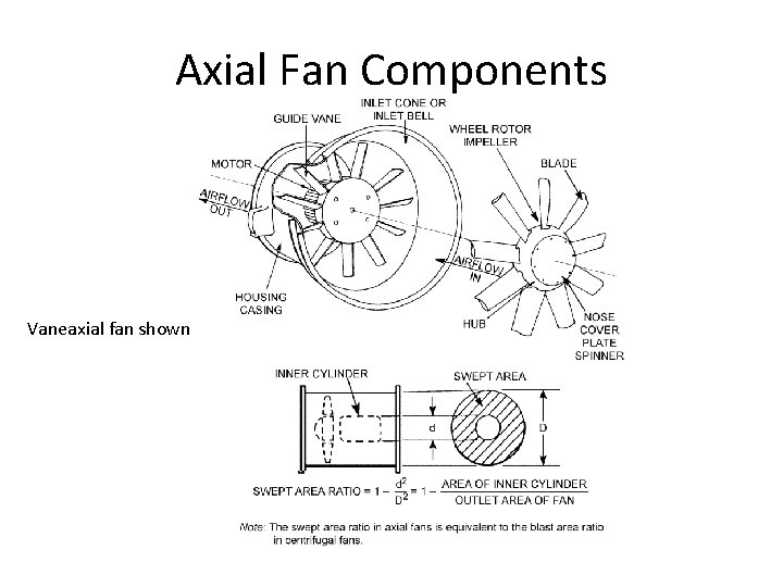
Air Moving Equipment: Fans and Ducts Types of axial fans ± Propeller • Move large volumes of air • Create very small pressure increases ± Tube axial • Propeller mounted in a tube ± Vaneaxial – low air turbulence
Air Moving Equipment: Fans and Ducts Performance characteristics of fans ± Volume ± Pressure ± Horsepower ± Speed ± Efficiency
Air Moving Equipment: Fans and Ducts Volume (capacity) ± Amount of airflow through the fan ± Expressed in cubic feet per minute (cfm) Pressure ± Potential and kinetic energy ± Pt = Ps + Pv (total, static, velocity)
Air Moving Equipment: Fans and Ducts Pressure sensing ± Static, Ps perpendicular to airflow ± Velocity, Pv parallel to airflow ± Total, Pt = Static, Ps + Velocity, Pv ± Pitot tube
Air Moving Equipment: Fans and Ducts Horsepower ± Brake horsepower ± Energy required to operate fans Speed ± Determines air volume ± Expressed in rotations per minute (rpm)
Air Moving Equipment: Fans and Ducts Efficiency ± Ratio of output to input ± Input is greater than output ± Friction losses effect efficiency ± Low friction losses high efficiency
Air Moving Equipment: Fans and Ducts Performance tables and curves for fans ± Compilation of fan characteristics ± Often called multi-rating tables ± Helps designers evaluate fan choices ± Horsepower, efficiency and pressure
Air Moving Equipment: Fans and Ducts Describing air flow in ducts ± Continuity principle • Q=Vx. A • Conservation of air mass ± Air velocity changes with duct size ± Larger ducts lower air velocity
Air Moving Equipment: Fans and Ducts Duct characteristics – ideal ± Increase in duct cross section • Velocity pressure drops • Static pressure increases • Total pressure remains constant
Air Moving Equipment: Fans and Ducts Duct characteristics – ideal ± Decrease in duct cross section • Velocity pressure increases • Static pressure drops • Total pressure remains constant
Air Moving Equipment: Fans and Ducts Duct characteristics – actual ± Friction causes pressure drops ± Larger ducts lower pressure drops ± Lower velocity lower pressure drops ± Turbulence causes pressure drops ± Static pressure drops as air flows
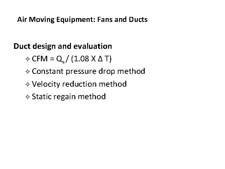
Air Moving Equipment: Fans and Ducts Duct design and evaluation ± CFM = Qs / (1. 08 X Δ T) ± Constant pressure drop method ± Velocity reduction method ± Static regain method
Air Moving Equipment: Fans and Ducts System performance and fan selection ± Airflow varies, duct system is fixed ± Friction increases at the square of flow rate ± System characteristic curve ± Operation point fan selection
Types of Fan Demo Two basic types of fan are: Centrifugal - rotating impeller to increase velocity of an airstream. Axial - air is pressurized by the aerodynamic lift of the fan blade.
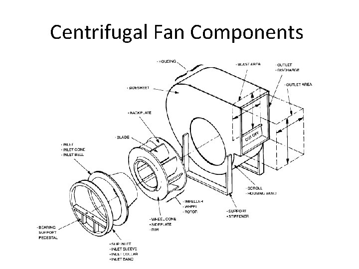
Centrifugal Fan Components
Axial Fan Components
Axial Fan Components Vaneaxial fan shown
Centrifugal Fans - Blade Designs
Centrifugal - Airfoil • Blade curves away from direction of rotation • Highest efficiency • Relatively low noise • High structural strength • Power reaches max near peak efficiency, then reduces twoards free delivery (self-limiting). • For given duty, has highest speed of centrifugal design
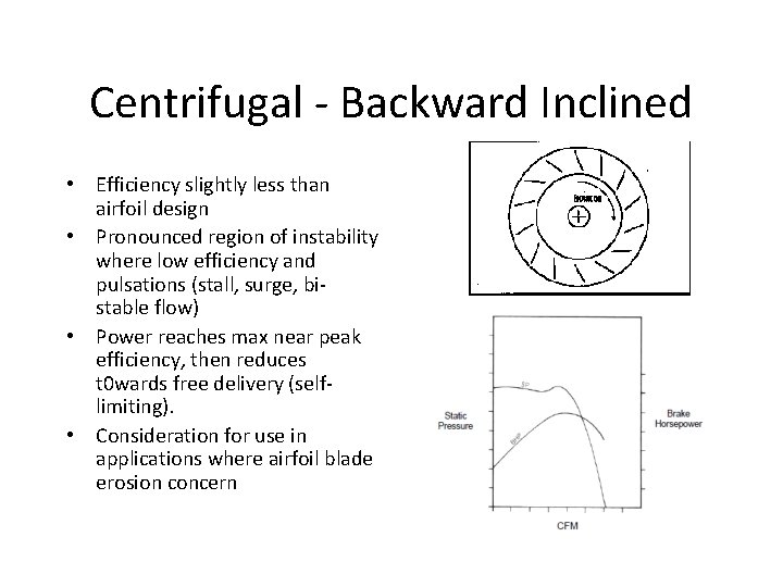
Centrifugal - Backward Inclined • Efficiency slightly less than airfoil design • Pronounced region of instability where low efficiency and pulsations (stall, surge, bistable flow) • Power reaches max near peak efficiency, then reduces t 0 wards free delivery (selflimiting). • Consideration for use in applications where airfoil blade erosion concern
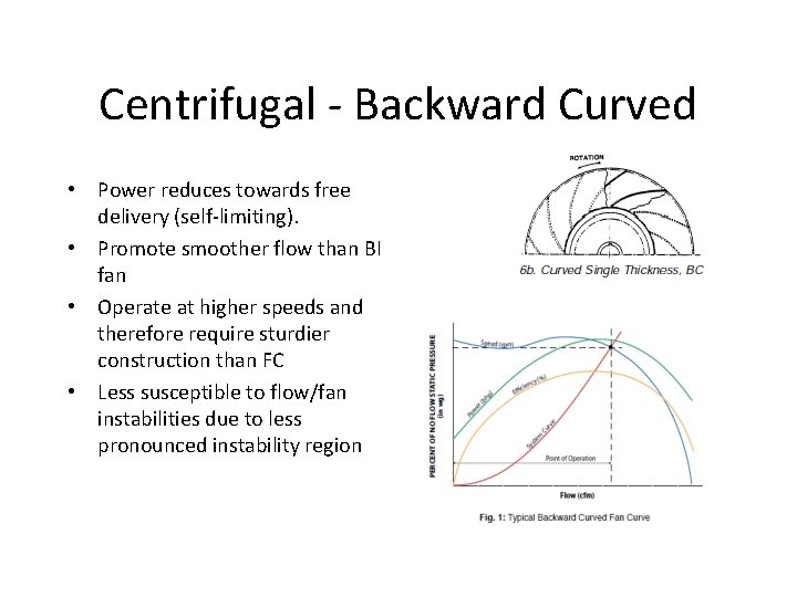
Centrifugal - Backward Curved • Power reduces towards free delivery (self-limiting). • Promote smoother flow than BI fan • Operate at higher speeds and therefore require sturdier construction than FC • Less susceptible to flow/fan instabilities due to less pronounced instability region
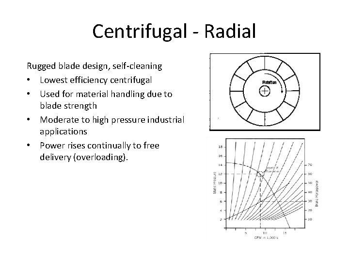
Centrifugal - Radial Rugged blade design, self-cleaning • Lowest efficiency centrifugal • Used for material handling due to blade strength • Moderate to high pressure industrial applications • Power rises continually to free delivery (overloading).
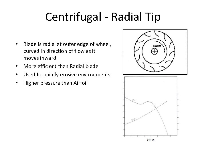
Centrifugal - Radial Tip • Blade is radial at outer edge of wheel, curved in direction of flow as it moves inward • More efficient than Radial blade • Used for mildly erosive environments • Higher pressure than Airfoil
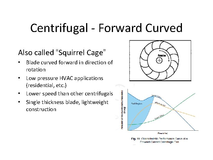
Centrifugal - Forward Curved Also called “Squirrel Cage” • Blade curved forward in direction of rotation • Low pressure HVAC applications (residential, etc. ) • Lower speed than other centrifugals • Single thickness blade, lightweight construction
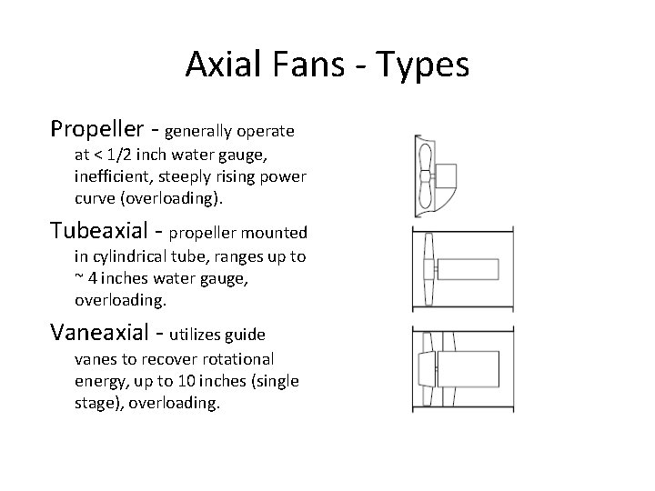
Axial Fans - Types Propeller - generally operate at < 1/2 inch water gauge, inefficient, steeply rising power curve (overloading). Tubeaxial - propeller mounted in cylindrical tube, ranges up to ~ 4 inches water gauge, overloading. Vaneaxial - utilizes guide vanes to recover rotational energy, up to 10 inches (single stage), overloading.
Axial Fan - Guide Vanes Function - reduce the helical flow pattern of the fan. Inlet - vanes guide airflow into a rotational pattern opposite to fan rotation to provide neutralize deflection by blades and result in axial flow Outlet - vanes take rotational pattern from blades and redirects it to an axial flow, converting some rotational velocity into static pressure.
Centrifugal Fan Volume Control Generally 3 methods: • Variable speed – changing fan speed results in a change in fan flow. • Outlet damper – functions by changing system resistance, forcing the fan to operate against higher backpressure and reducing the flow. • Inlet damper – combination of resistance change and potential flow characterisitic change (spin, reduced turbulence) at fan inlet.