How does seismic design impact steel weight Mingjian


, but")


 Beam flange must be reduced 2) Beam web")


: Seismic design usually increase total steel weight of structure, it’s rare to")


: Allowing for structural steelequipment interaction effect is accurate way to analyze, but steel")


: Principle to seismic design: try to avoid seismic design as much as possible")

- Slides: 40
How does seismic design impact steel weight? Mingjian Jin 8 Nov. , 2017
Codes cover seismic design: IBC, ASCE 7, AISC 341 and AISC 358
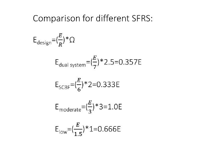
Symbol and abbreviation: E=elastic seismic response R=Response modification coefficient Ω=overstrength factor SCBF=special concentrically braced frame SMF=special moment frame SFRS=seismic force resisting system
Typical parameters for seismic design: R=7, Ω=2. 5 for dual system, SCBF+SMF, highest dissipative capability R=6, Ω=2 for SCBF, high dissipative capability
Typical parameters for Non-seismic design: R=3, Ω=3 for moderate dissipative capability R=1. 5, Ω=1 for low dissipative capability
Seismic design induces: smaller SFRS member size (except for special beam between columns), but non-SFRS member size reduces a little because seismic action mainly affects SFRS only.
Non-linear behaviour of structure is required to allow for: Seismic internal force will be redistributed when compressive vertical brace buckles.
Beam between columns along re-distributed seismic force transfer path is subject to heavy axial compression due to resulting force from tensile yielding VB member and compressive post-buckling VB member. It increases steel weight of those beams significantly.
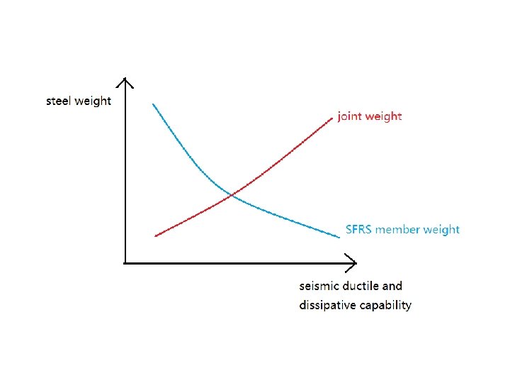
Comparison for joint design: analytical force for non-seismic joint design Capacity force for seismic joint design capacity force is very much higher than analytical force. It results in quite big joint dimension and quite heavy joint weight.
Below are seismic detailing requirements…
This is a typical and normal VB joint, which is very compact and materialsaving, but unfortunately it is not allowed by seismic design.
2 t straight line clear distance is required to let VB gusset plate out-of-plane buckle, t is thickness of gusset plate. It results in quite big VB gusset plate.
Alternatively, 8 t elliptical clear distance is required to let VB gusset plate undergo out-ofplane buckling, t is thickness of gusset plate. It helps a little, often gives same result as 2 t straight line clear distance.
It’s very difficult to achieve tartget of stronger column, weaker beam when subject to heavy equipment load.
Above examples are from AISC 341. meanwhile more examples of severe seismic detailing requirements are from AISC 358.
Prequalified joint for welded connection: 1) Beam flange must be reduced 2) Beam web must be welded to column Disadvantage: Customer usually doesn’t allow welding on site
Disadvantage: Geometry limitations on reduced beam joint are difficult to be satisfied.
Prequalified joint for bolted connection: There’re only 3 options for end plate configuration Disadvantage: Not applicable to heavy load
Geometry limitations on end plate joint are quite difficult to be satisfied.
What will happen if joint configuration is out of prequalified limitation of AISC 358?
Impact from seismic joint design: capacity force design induces heavy joint dimension and weight. Seismic detailing requirements induce heavy joint dimension and weight also. Possible physical test or FE-analysis, paper, approval procedure for prequalification is cost increase and schedule risky.
In special cases, e. g. X-brace system, steel weight of joint is very easy to exceed that of member.
Summary (1): Seismic design usually increase total steel weight of structure, it’s rare to see decrease of it.
Equipment-steel interaction model
Equipment-steel interaction model undergoes seismic drift
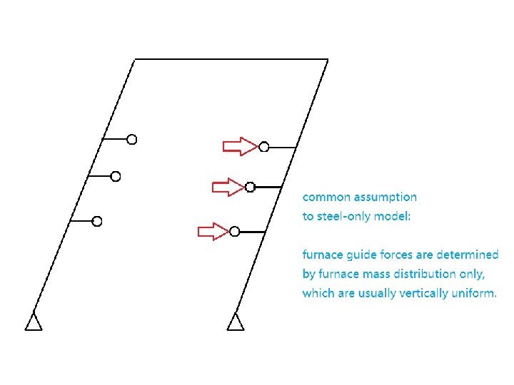
Steel-only model undergoes seismic drift
The figure shows: interaction forces between equipment and structural steel frame
Guide forces in equipment-steel interaction model are determined not only by furnace mass distribution, but also by shear and bending stiffness of furnace membrane and relative stiffness of guide system in different levels. User can manually adjust guide force vertical distribution by adjusting laterally translational stiffness of guides. Sometimes user gets higher guide force than steel-only model, sometimes user gets lower guide force than steel-only model.
Summary(2): Allowing for structural steelequipment interaction effect is accurate way to analyze, but steel weight increase is possible, as well as weight of furnace buckstay system.
Further discussion on application of seismic design…
IBC code requests compulsory seismic design for Seismic Design Category D, E, F in any case.
ASCE allows excluding seismic design from building for Seismic Design Category A, B, C when R=3.
ASCE allows excluding seismic design from nonbuilding for any Seismic Design Category when R=1. 5.
Summary(3): Principle to seismic design: try to avoid seismic design as much as possible by selecting low dissipative capacity for the structure • Exclude seismic design towards SDC category A, B, C. • Designer evaluates impact of seismic design and decide whether excluding it towards SDC category D, E, F.
Thank you very much!