gggg Soil mechanics and Advanced Foundation Design and


0. 25 = 3. 5 (8. 25/18)0.")


- Slides: 22
gggg Soil mechanics and Advanced Foundation
Design and Detailing of Counterfort Retaining wall
Counterfort Retaining wall • • • When H exceeds about 7 m, Stem and heel thickness is more More bending and more steel Cantilever-T type-Uneconomical Counterforts-Trapezoidal section 1. 5 m -3 m c/c CF Stem Base Slab CRW 3
Parts of CRW • Same as that of Cantilever Retaining wall Plus Counterfort Stem Counterforts Heel Toe Base slab Cross section Plan 4
Design of Stem • The stem acts as a continuous slab • Soil pressure acts as the load on the slab. • Earth pressure varies linearly over the height • The slab deflects away from the earth face between the counterforts • The bending moment in the stem is maximum at the base and reduces towards top. BF p=Kaγh 5
Maximum Bending moments for stem • Maximum + B. M= pl 2/16 • (occurring mid-way between counterforts) • and • Maximum - B. M= pl 2/12 • (occurring at inner face of counterforts) l + • Where ‘l’ is the clear distance between the counterforts • and ‘p’ is the intensity of soil pressure 6 p
Design of Toe Slab • The base width=b =0. 6 H to 0. 7 H • The projection=1/3 to 1/4 of base width. • The toe slab is subjected to an upward soil reaction and is designed as a cantilever slab fixed at the front face of the stem. • Reinforcement is provided on earth face along the length of the toe slab. • In case the toe slab projection is large i. e. > b/3, front counterforts are provided above the toe slab and the slab is designed as a continuous horizontal slab spanning between the front counterforts. H b 7
Design of Heel Slab • The heel slab is designed as a continuous slab spanning over the counterforts and is subjected to downward forces due to weight of soil plus self weight of slab and an upward force due to soil reaction. • Maximum -ve B. M= pl 2/12 Maximum +ve B. M=pl 2/16 • (mid-way between counterforts) • And • (occurring at counterforts) BF 8
Design of Counterforts • The counterforts are subjected to outward reaction from the stem. • This produces tension along the outer sloping face of the counterforts. • The inner face supporting the stem is in compression. Thus counterforts are designed as a T-beam of varying depth. • The main steel provided along the sloping face shall be anchored properly at both ends. • The depth of the counterfort is measured perpendicular to the sloping side. C T d 9
Behaviour of Counterfort RW -M Important points +M • Loads on Wall COUNTERFORT • Deflected shape STEM • Position of steel -M • Counterfort details HEEL SLAB TOE +M 10
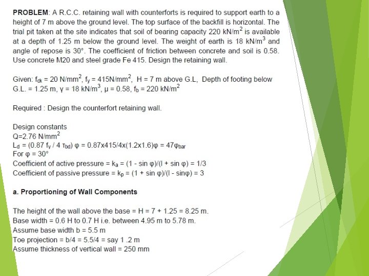
a. Proportioning of Wall Components • • • Coefficient of active pressure = ka = 1/3 Coefficient of passive pressure= kp = 3 The height of the wall above the base = H = 7 + 1. 25 = 8. 25 m. Base width = 0. 6 H to 0. 7 H h 1 = 7 m H (4. 95 m to 5. 78 m), Say b = 5. 5 m Toe projection = b/4 = 5. 5/4 = say 1. 2 m Assume thickness of vertical wall = 250 mm Thickness of base slab = 450 mm 1. 25 m b=5. 5 m 12
Spacing of counterforts l = 3. 5 (H/γ)0. 25 = 3. 5 (8. 25/18)0. 25 = 2. 88 m c/c spacing = 2. 88 + 0. 40 = 3. 28 m say 3 m l Provide counterforts at 3 m c/c. Assume width of counterfort = 400 mm clear spacing provided = l = 3 - 0. 4 = 2. 6 m 13
Details of wall 250 mm CF: 3 m c/c, 400 mm h 1=7 m h=7. 8 m H=8. 25 m d 1. 25 m T 1. 2 m 4. 05 m θ b=5. 5 m 14
b. Check Stability of Wall Loads in k. N Dist. of e. g. from T in m Moment about T in k. N-m Weight of stem W 1 25 x 0. 25 x 1 x 7. 8 = 48. 75 1. 2 + 0. 25/2 =1. 325 64. 59 2 Weight of base slab W 2 25 x 5. 5 x 1 x 0. 45 = 61. 88 5. 5/2 =2. 75 170. 17 3 Weight of earth over heel slab W 3 18 x 4. 05 x 1 x 7. 8 = 568. 62 1. 45 +4. 05/2 = 3. 475 1975. 95 Sr. No. Description of loads 1 Total ΣW =2210. 71 ΣW = 679. 25 15
250 mm W 1 W 3 H 8250 h 1= 7000 ΣW R PA Df= 1250 A 1200 mm B C 450 4050 mm PA D H/3 W 2 T X e b/3 ka H b/2 Pressure distribution Cross section of wall-Stability analysis 16
Stability of walls • Horizontal earth pressure on full height of wall • = Ph = ka H 2 /2 =18 x 8. 252/(3 x 2) = 204. 19 k. N • Overturning moment = M 0 • = Ph x H/3 = 204. 19 x 8. 25/3 = 561. 52 k. N. m. • Factor of safety against overturning • = ∑ M / M 0 = 2210. 71/561. 52 = 3. 94 > 1. 5 � safe.
Check for sliding Total horizontal force tending to slide the wall = Ph = 204. 19 k. N Resisting force = ∑µ. W = 0. 58 x 679. 25 = 393. 97 k. N Factor of safety against sliding = ∑µ. W / Ph = 393. 97/204. 19 = 1. 93 > 1. 55. . . safe. 18
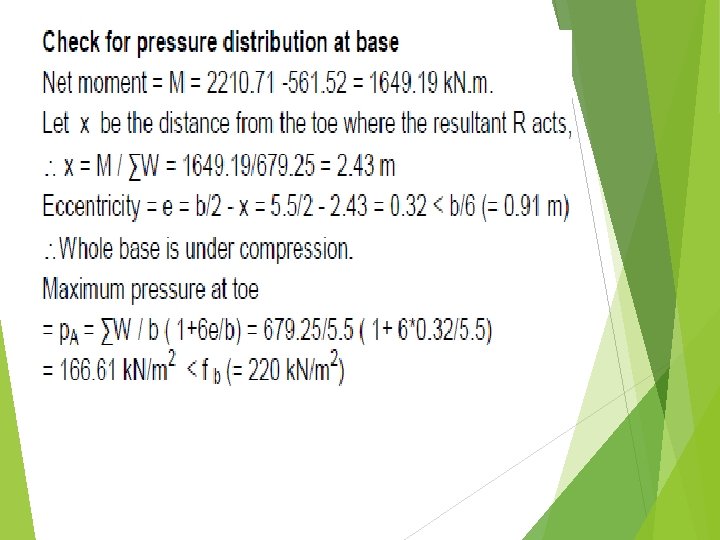
Check for pressure distribution at base 19
250 mm H 8250 ΣW R PA A 1200 mm. B 12 C 4050 mm D 450 T X e 166. 61 153. 9 147. 8 143. 9 k. N/m 2 b/2 80. 39 k. N/m 2 5500 mm 21