GDOT Approach to Wall Foundation Investigations LRFD Methodology


 was used generally in the US for foundation")


 Footing Thickness, t (ft) Layer")


- Slides: 26
GDOT Approach to Wall Foundation Investigations LRFD Methodology Adebola Adelakun, E. I. T. , MSCE
Presentation Outline • History • GDOT Approach Phase 1 - Soil Parameters Phase 2 - WFI Analysis • Report Recommendation
History • Allowable Stress Design (ASD) was used generally in the US for foundation design • Work began on developing Load and Resistance Factor Design (LRFD) in 1989 • In 1994, AASHTO approved LRFD spec. for use
History Cont’d • In 2000, FHWA required all DOTs to design structures in LRFD for PE authorized projects let after October 1, 2007, or provide justification and a timeline • GDOT first developed an LRFD process for deep foundations, and subsequently a process for shallow foundations
GDOT Approach Phase 1 - Foundation & Retained Soil Parameters Wall Envelope Geotechnical Investigation Boring Logs Soil Parameters Phase 2 – WFI Analysis and Report Foundation Design Data Factored Bearing Resistance Analysis Settlement Analysis Differential Settlement Analysis WFI Report
Phase 1 – Wall Envelope The WFI process starts with receiving a Wall Envelope from the Bridge Office
Phase 1 – Geotechnical Investigation • Drilling • Soil/Rock Sample Examination • Lab Tests
Phase 1 - Boring Logs
Phase 1 – Wall Soil Parameters Foundation & Retained Soil Parameter Letter • We determine soil parameters based on the following: – Geotechnical investigation/geology – Finished boring logs – Shallow Foundations LRFD Spreadsheet • A letter to the bridge office stating the following soil parameters (for foundation & retained soil): – Soil Unit Weight – Internal Friction Angle – Cohesion (Usually Zero)
Soil Parameter Calculations
End of Phase 1
Phase 2
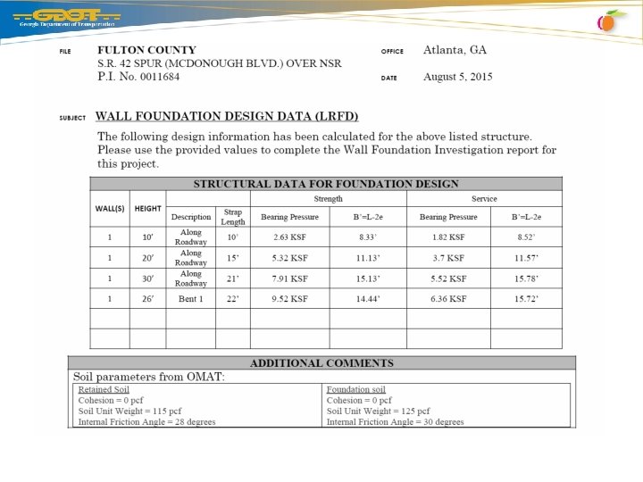
Phase 2 – WFI Analysis and Report Foundation Design Data Letter received from Bridge Office contains: • Wall Heights • Base Width/Strap Lengths (MSE Walls) • Bearing Pressure (Strength and Service Limit States) • Effective Base Width/Strap Lengths (Strength and Service Limit States) – due to “eccentricity”
Divide Wall into Height Sections
“Input” Tab on Spreadsheet Perform analysis per ‘wall height’ section Enter: • Project info • GWT (boring log) and Energy Rating (from Driller) • Footing length (from wall envelope) • Footing width (from fdtn design data letter) • Specific settlement values (start w/ 0. 5 in increments) • Footing input parameters • Boring log (when you have multiple logs, use log closest to current wall section being analyzed)
Sample Energy Rating Submittal
Footing Input Parameters • • Embedment Depth, Df (ft) Footing Thickness, t (ft) Layer Thickness, H (ft) Elastic Modulus of Foundation Material, Efdtn (ksf) – 600, 000 for Concrete or 4000 for MSE Wall Backfill
Clay Soils
Phase 2 – WFI Analysis and Report •
Phase 2 – WFI Analysis and Report •
Output • The 30 feet high Wall Section has a 21 feet Footing Width (Strap Length) • The bearing pressure (strength) for this wall section is 7. 91 ksf • After analysis, the graph is showing that if we control for 8 inches of settlement, we will get 8. 06 ksf in bearing resistance (> 7. 91, so its ok)
Phase 2 – WFI Analysis and Report Differential Settlement Analysis (C 11. 10. 4. 1 -1 & C 11. 6. 2. 2) • The ratio of the difference in settlement of adjacent wall sections and their horizontal distance • Purpose is to avoid overstressing the wall - a section of wall could potentially cause other sections or the entire wall system to fail • Limit for MSE Walls is 1/100 (<0. 01) • Limit for Conventional Retaining walls is 1/1000 (<0. 001)
Differential Settlement Check
WFI Report Recommendation
The End Any Questions?