Load and Resistance Factor Design LRFD Resistance Factors
 Resistance Factors for Tip Grouted Drilled Shafts BDV")


 Taipei 101 (Taiwan) Flagler (Florida)")
")


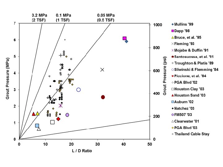
 • Design Method – Grout pressure / side shear")


 0 Bias (measured / predicted)")


- Slides: 43
Load and Resistance Factor Design (LRFD) Resistance Factors for Tip Grouted Drilled Shafts BDV 25 TWO 977 -37 GRIP 2017
Outline • Problem Statement • Background – Grouting Basics – Grouting Systems – Grouting Methods • • • Expected Grouting Performance Design Methods Resistance Factors Tasks Schedule
Problem Statement • Like all capacity prediction methods, the postgrouted end bearing of drilled shafts has inherent uncertainty. • Both the design and construction practices are affected • No resistance factors (or safety factors) are in place to moderate the uncertainty associated with varying design or grouting methods
Grouting Basics Grout Pump
Uplift Pressure
Uplift Pressure Volume
Uplift Pressure Volume
Uplift Pressure Volume
Uplift Pressure Volume
Uplift Pressure Volume
Effectiveness Plots Expected Results
Grouting systems Sutong (China) Taipei 101 (Taiwan) Flagler (Florida)
Grouting systems Flat jack (open or closed)
Grouting Method • Attach distribution system to cage • Construct shaft in normal fashion • Flush grout distribution system (burst sleeve ports) before concrete has full strength • Cure concrete • Pump neat cement grout through lines demonstrating system is clear, close return valves and pump grout until design pressure is achieved • Record: volume, pressure, uplift and strain at prescribed intervals (e. g. 10 data points up to design pressure)
Grout Mixer / Plant High Energy Colloidal Mixer Storage / Agitation Tank Piston Pump Hydraulic Power
Grout Test Data Collection eference Beam Displacement Gages
Grouting Methods Flush with clean water
Grout return
Field Practice / Design Expectation • Grout pressure is intended to create an expanding bulb of grout where pressure increases with size of bulb • If pressure is not achieved, stage grouting is often suggested • Stage grouting reduces the size of the active/liquid grout pressure area and does not continue to increase soil improvement • Design methods implicitly assign capacity gains on a combination of increases in tip area and soil strength • Designer must be aware of this global effect
Best Case Effect of Stage Grouting
Undesired Result of Stage Grouting
Design Methods Three Basic Approaches • Unit end bearing = Grout pressure • Unit end bearing function of grout pressure and displacement – Single stage grouting Mullins et al. 2006 – Multi-stage grouting Dapp and Brown, 2010
Design Methods •
Grouting Effectiveness or Design Method
Grouting Effectiveness or Design Method
Uplift Pressure
Uplift Pressure
Uplift Pressure
Uplift Pressure
Uplift Pressure
Uplift Pressure
Uplift Pressure
Grouting Effectiveness or Design Method
Factors Affecting Resistance Factor (measured/predicted) • Design Method – Grout pressure / side shear prediction – End bearing prediction • Displacement – Not a single capacity – Davisson method not applicable • Field Method – Single or multi stage • Grouting Effectiveness – Effectiveness plot verification • Frequency of Load Testing
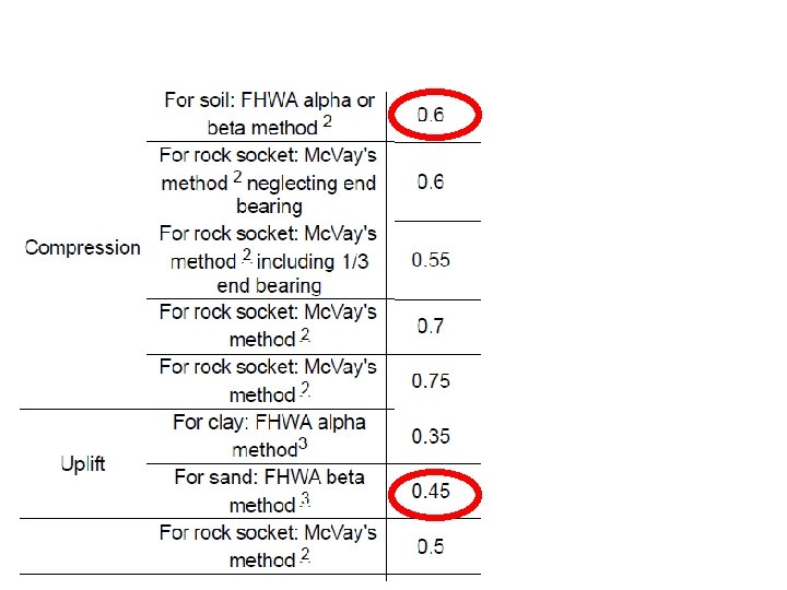
Soils and Foundations Handbook “Resistance factors and associated design methods for geotechnical resistance of drilled shafts are in SDG Table 3. 6. 3 -1 [Table 2. 3]. It is implicitly shown in the table that the resistance factors for drilled shafts tipped in sand or clay are based on side shear design methods only (i. e. FHWA alpha method in clay and FHWA beta method in sand). ”
Soils and Foundations Handbook “In sand, drilled shafts with pressure grouted tips should be considered. Pressure grouted tips are most effective in loose to medium dense sands. Guidance for the design of drilled shafts with pressure grouted tips may be found in Appendix D and in Reference 9. ” No Resistance Factor is directly associated with PG shafts; rather that from the load test method is used.
Types of Resistance Factors • End Bearing Variables – End bearing is function of pressure – Pressure achieved on first or multiple stages – Field verification testing , and – Present, load test dependent • Grout Pressure / Side Shear – Pressure is function of: • side shear, and • end bearing strata – Side shear in uplift, no reduction presently used
Design / Field / Reliability Unit End Bearing (tsf) 0 Bias (measured / predicted) 10 20 30 40 50 60 70 80 90 0 0. 5 1. 5 2 2. 5 Shaft No 2 Shaft No 5 Shaft No 6 3 3. 5 4 Mullins et al Dapp and Brown Displacement (%D) 1
Work Plan • • • Task 1. Literature Review Task 2. Collect Post Grouting Case Study Data Task 3. Process Data / Analysis Task 4. Recommendations and Guidelines Task 5. Draft Report / Close-out Meeting Task 6. Final Report
Schedule Description Date Project Kickoff Teleconference / Presentation webinar Task 1: Literature Review. February 2017 June 2017 Task 2. Collect Geotechnical Design Information. November 2017 Task 3. Process Data and Analysis April 2018 Task 4: Conclusions and Recommendations October 2018 Task 5 a: Draft Final Report October 2018 Deliverable 5 b – Closeout Meeting / Presentation Deliverable 6 – Final Report January 2019
Questions