FUNDAMENTALS OF NETWORKING CHAPTER 4 TRANSMISSION MODE TRANSMISSION


- Slides: 27

FUNDAMENTALS OF NETWORKING CHAPTER 4 TRANSMISSION MODE & TRANSMISSION FUNCTION

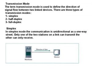
TRANSMISSION DIRECTION The flow of data must be controlled in some way so that the sending and receiving stations know when they will receive data or when they should send data. Simplex Transmission Half-Duplex Transmission Full-Duplex Transmission

Simplex Transmission A simplex connection is a connection in which the data flows in only one direction, from the transmitter to the receiver. This type of connection is useful if the data do not need to flow in both directions (for example, from your computer to the printer or from the mouse to your computer

HALF- DUPLEX A half-duplex connection (sometimes called an alternating connection or semi-duplex) is a connection in which the data flows in one direction or the other, but not both at the same time. With this type of connection, each end of the connection transmits in turn. This type of connection makes it possible to have bidirectional communications using the full capacity of the line.

FULL- DUPLEX A full-duplex connection is a connection in which the data flow in both directions simultaneously. Each end of the line can thus transmit and receive at the same time, which means that the bandwidth is divided in two for each direction of data transmission if the same transmission medium is used for both directions of transmission.

Multiplexer & Demultiplexer Multiplexer : device that receive the input signals from several devices, combines them into a single stream of data, and then transmits the data over a single communication line. Demultiplexer: recovers the input signals and presents them as separate signals again.

Frequency Division Multiplexing Several signals are joined for transmission on one communication line or channel The bandwidth at the entire communications line is divided into narrower bandwidth, or channels so each client on the line can use one frequency range to transmit data * A guardband is a range of frequency that prevents the current containing the data from one transmission from interfering with another transmission current on the same line.

Time Division Multiplexing TDM divides the transmission time slot into time segment Multiplexer repeatedly transmits a fixed sequence of time slots over a single transmission channels. Each client is assigned a fixed time slot in the rotation during which it can transmit data, and the client is given the full transmission capacity of the line for that given time.

Time Division Multiplexing (cont. ) A major difference between TDM and FDM is that, instead of using frequency guardband to separate the signal, TDM uses “ times” to separate the signal If a client has no data to transmit during its fixed time slot, the transmission line remains idle during that time, and no other client can use that time slot. For most application, client do not transmit continuously. In this case, TDM means some section of transmission line always idle.

Statistical Time Division Multiplexing Time slots are assigned to client on the network dynamically. The difference is that the time slots is not fixed. TDM is driven by time, STDM is driven by data.

Wavelength Division Multiplexing A type multiplexing developed for both digital signal and analog transmission on fibre optic cables. In WDM, each signal is assigned to a particular wavelength on an optical fiber communication line. By using different frequency within optical bandwidth, many different transmission can exist on same individually cladded optical fibre

Frequency Division Multiple Access Wireless communication also make use of multiplexing systems to allow multiple access with the potential for multiple users to access any available cellular frequency or channel. More efficient and cost effective than reserving a unique frequency for each subscriber. The oldest multiple access technology and the most commonly used for analog cellular communication.

Frequency Division Multiple Access(Cont. ) In other words, if cellular subscriber is using a particular frequency for a call, no other subscriber can use the same frequency to make different call until first call is terminated, or until the first caller moves into different cell. Others callers still can transmit on other available channels, however.

Time Division Multiple Access In order to increase efficiency of digital cellular systems used today, TDMA methodology was developed. TDMA operates in a manner similar to TDM, except that it is was designed for cellular radio, rather than for guided media. With TDMA, the radio signal is divided into time slots to increase the amount of data that can be carried and allow multiple users to access the same frequency simultaneously. Although TDMA enables only three users within a given a cell to use the same frequency, the added capacity makes the system cost-efficient.

Code Division Multiple Access A more recent development, used in second generation (2 G) and third generation (3 G) wireless technology. CDMA assigns each conversation a unique code. Both the mobile telephone and the communication systems at the base station use this code to identify signals that are part of the conversation. Used direct sequence spread spectrum technology, meaning that the original signal is spread over several frequency simultaneously. Although CDMA does have some capacity limitations, no maximum number of calls per single, wide bandwidth channel is established. The number of calls that a channel can accommodate is based on the total bandwidth of the channel, the required geographical coverage and the quality of sound.

Modulation • modulation is the process of varying one or more properties of a high-frequency periodic waveform, called the carrier signal, with a modulating signal which typically contains information to be transmitted • In telecommunications, modulation is the process of conveying a message signal, for example a digital bit stream or an analog audio signal, inside another signal that can be physically transmitted

Analog Modulation • Analog data is transmitted on any communications medium by means of an electrical signal called carrier signal. • The change made to the signal is called signal modulation, or modulation. • Three types of modulation are – Amplitude Modulation (AM) – Frequency Modulation (FM) – Phase Modulation (PM)

Amplitude Modulation (AM) refers to a change in the height of the carrier wave for analog signals. When data is sent to the carrier signal, the height of the signal is changed to indicate a 0 bit or a 1 bit. The highest peaks of the signal represent a 1 bit, and the lowest peak represents a 0 bit.

Frequency Modulation (FM) Refers to the number of waved used to represent a single cycle. The number of waves changes for a 0 bit or a 1 bit; this change in frequency is indicated by a difference in the tone of the signal. A higher tone indicates more waves per unit of time and a lower tone indicate fewer waves per unit of time.

Phase Modulation A phase shift occurs to indicate a change in the type of bits being transmitted. To indicate a 1 bit, the wave moves in a specific direction. When a 0 bit is detected, the direction of the wave changes 180 O

Digital Modulation Digital data must be converted to an analog form to be transmitted on an analog transmission medium

Using Analog Signal to Transmit Digital Data • When amplitude modulations converts digital signals into a form that can be transmitted on an analog line, “Amplitude-shift keying (ASK)” • When digital signals modulate using the frequency modulation technique, “Frequency-shift keying (FSK)” • Digital data that changes using phase modulation is called “Phase-shift keying (PSK)”. • Another type of digital phase modulation is called “Differential phase-shift keying (DPSK)”.

Using Digital Signals to Transmit Analog Data • The most common form today – Pulse Code modulation. – PAM is performed on the data to get a sampled signal. – Then the signal is quantized (assigning integer values within a range to the samples). – The quantization assigns values of 0 to 255, depending on the amplitude of the signal at the instant that it is sampled. – The values then are converted to their binary equivalent, and the digital signal thus is encoded.

Using Digital Signals to Transmit Digital Data To transmit the 1 s and 0 s generated by the computer, even in a digital form, the bit must be changed into a digital signal. Three types of conversion for digital signals Unipolar Polar Bipolar

Synchronous transmission The term synchronous is used to describe a continuous and consistent timed transfer of data blocks. These types of connections are used when large amounts of data must be transferred very quickly from one location to the other. The speed of the synchronous connection is attained by transferring data in large blocks instead of individual characters. The data blocks are grouped and spaced in regular intervals and are preceded by special characters called syn or synchronous idle characters. See the following illustration. Figure 1. Synchronous transmission

Synchronous transmission (Cont. ) After the syn characters are received by the remote device, they are decoded and used to synchronize the connection. After the connection is correctly synchronized, data transmission may begin. An analogy of this type of connection would be the transmission of a large text document. Before the document is transferred across the synchronous line, it is first broken into blocks of sentences or paragraphs. The blocks are then sent over the communication link to the remote site. With other transmission modes, the text is organized into long strings of letters (or characters) that make up the words within the sentences and paragraphs. These characters are sent over the communication link one at a time and reassembled at the remote location. The timing needed for synchronous connections is obtained from the devices located on the communication link. All devices on the synchronous link must be set to the same clocking.

Synchronous transmission (Cont. ) The timing needed for synchronous connections is obtained from the devices located on the communication link. All devices on the synchronous link must be set to the same clocking. The following is a list of characteristics specific to synchronous communication: ü There are no gaps between characters being transmitted. ü Timing is supplied by modems or other devices at each end of the connection. ü Special syn characters precede the data being transmitted. ü The syn characters are used between blocks of data for timing purposes.
 A mode ultrasound uses
 Three dumb routers
 Web
Web Networking osi model
 Ccna
Ccna Networking fundamentals
 Transmission basics and networking media
 Describe manual transmission fundamentals.
 Hep b mode of transmission
 Blepharoblast
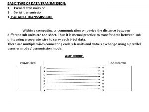
 Parallel transmission mode
 Parallel transmission mode
 Focus mode and diffuse mode
 Mode địa chỉ tức thì là mode
 Difference between real protected and virtual mode of 80386
 What is the operation for mode 0?
 Gartner mode 1 mode 2
 Perbedaan (planning mode) dan (evolutionary mode)
 Min mode and max mode in 8086
 Nursing chapter 1
 Fundamentals of electric circuits chapter 4 solutions
 Fundamentals of corporate finance chapter 6 solutions
 Digital fundamentals chapter 4
 Conceptual physics magnetism
 Chapter 73 tire wheel and wheel bearing fundamentals
 Goodheart willcox chapter 1 answers
 Fundamentals of electric circuits chapter 9 solutions
 Fundamentals of electric circuits chapter 7 solutions
