Foto Rona Proudfoot some rights reserved Datorarkitektur 11






- Slides: 40
Foto: Rona Proudfoot (some rights reserved) Datorarkitektur 11 & & Datorsystem 11 –– föreläsning 10 10 onsdag 14 14 november 2007
1977
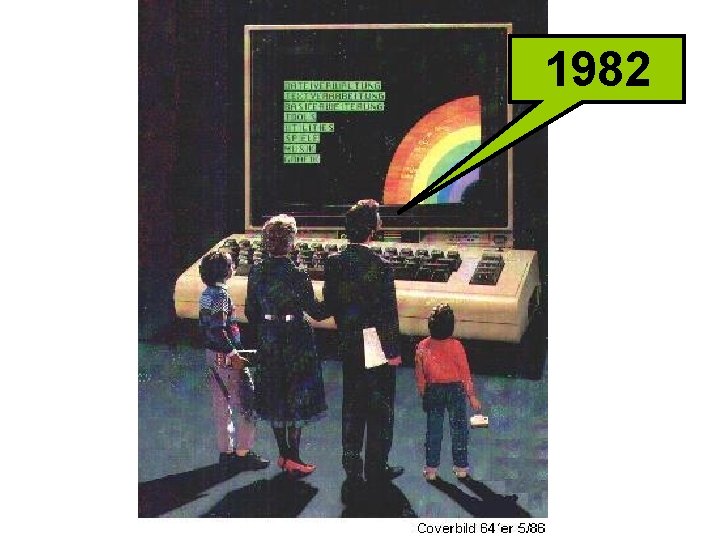
1982
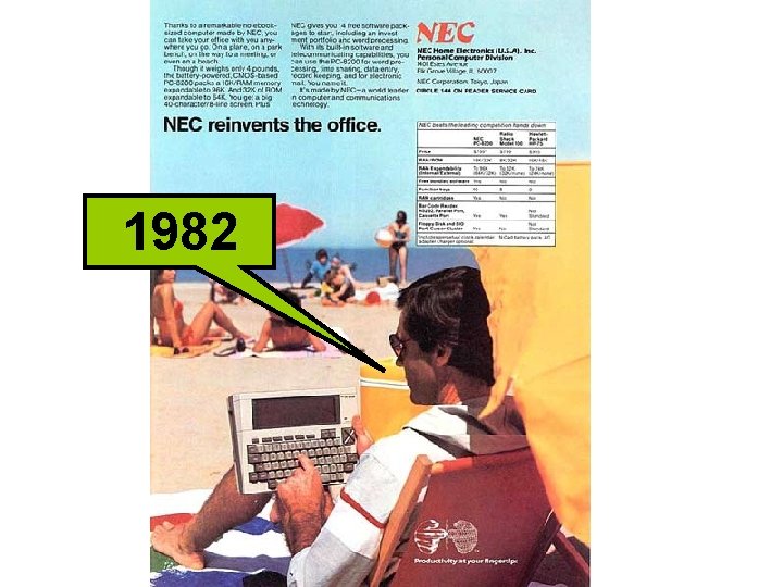
1982
1982
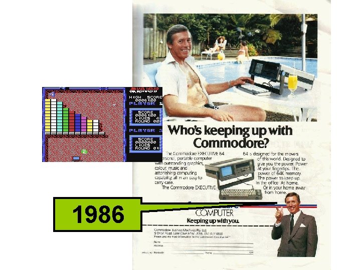
1986
1986
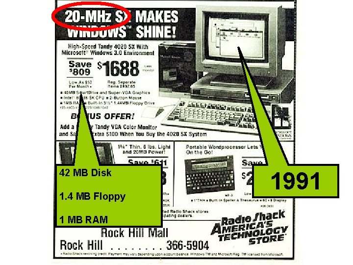
42 MB Disk 1. 4 MB Floppy 1 MB RAM 1991
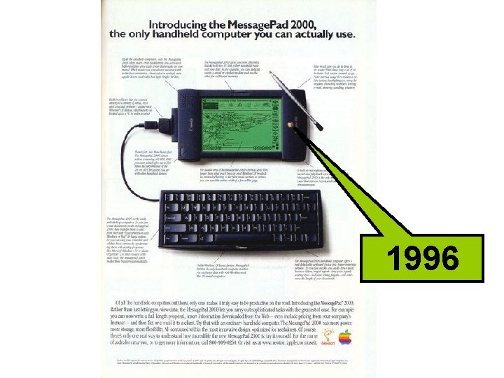
1996
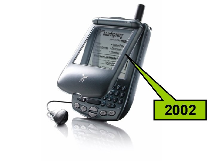
2002
2007
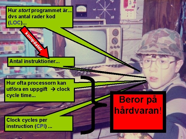
Vad bestämmer om ett program körs snabbt eller långsamt?
Hur stort programmet är. . . dvs antal rader kod (LOC). . . r to la pi m ko Antal instruktioner. . . Hur ofta processorn kan utföra en uppgift clock cycle time. . . Clock cycles per instruction (CPI). . . Beror på hårdvaran!
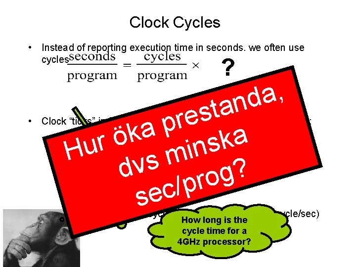
Clock Cycles • Instead of reporting execution time in seconds, we often use cycles ? , a d n a t s e r p a k a ö k r s u n i H m s dv ? g o r p / c e s • Clock “ticks” indicate when to start activities (one abstraction): time cycle time = seconds per cycle • clock rate (frequency) = cycles per second (1 Hz = 1 cycle/sec) How long is the cycle time for a 4 GHz processor?
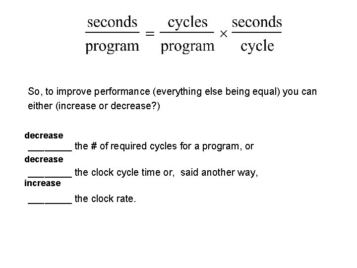
So, to improve performance (everything else being equal) you can either (increase or decrease? ) decrease ____ the # of required cycles for a program, or decrease ____ the clock cycle time or, said another way, increase ____ the clock rate.
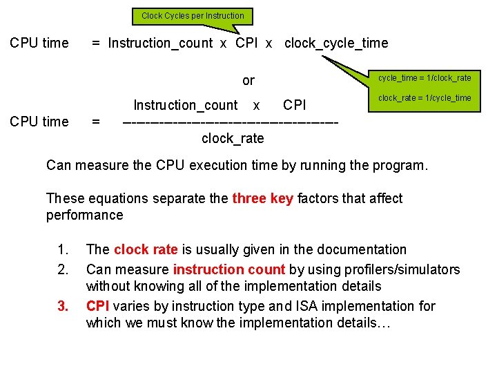
Clock Cycles per Instruction CPU time = Instruction_count x CPI x clock_cycle_time or CPU time = Instruction_count x CPI -----------------------clock_rate cycle_time = 1/clock_rate = 1/cycle_time Can measure the CPU execution time by running the program. These equations separate three key factors that affect performance 1. 2. 3. The clock rate is usually given in the documentation Can measure instruction count by using profilers/simulators without knowing all of the implementation details CPI varies by instruction type and ISA implementation for which we must know the implementation details…
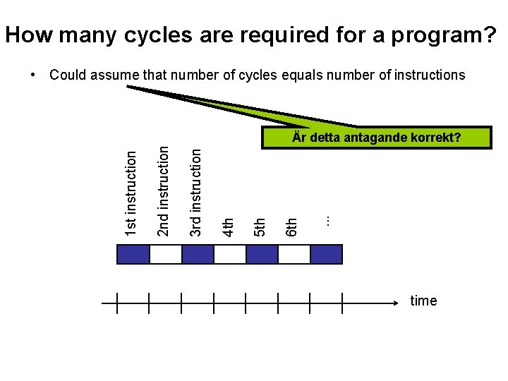
How many cycles are required for a program? • Could assume that number of cycles equals number of instructions . . . 6 th 5 th 4 th 3 rd instruction 2 nd instruction 1 st instruction Är detta antagande korrekt? time
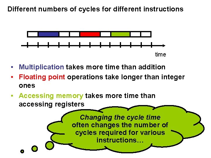
Different numbers of cycles for different instructions time • Multiplication takes more time than addition • Floating point operations take longer than integer ones • Accessing memory takes more time than accessing registers Changing the cycle time often changes the number of cycles required for various instructions…
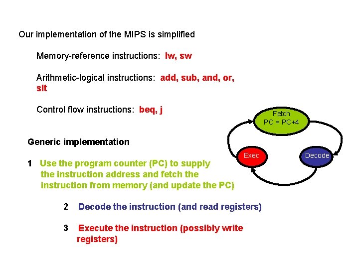
Our implementation of the MIPS is simplified Memory-reference instructions: lw, sw Arithmetic-logical instructions: add, sub, and, or, slt Control flow instructions: beq, j Fetch PC = PC+4 Generic implementation 1 Use the program counter (PC) to supply the instruction address and fetch the instruction from memory (and update the PC) Exec 2 Decode the instruction (and read registers) 3 Execute the instruction (possibly write registers) Decode
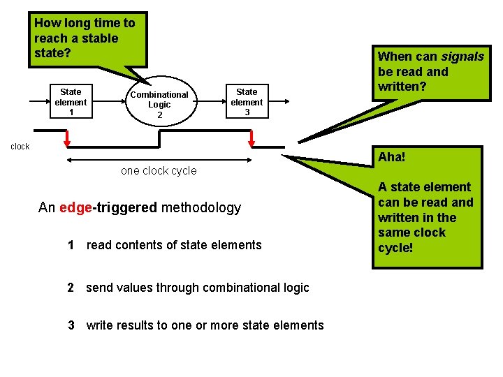
How long time to reach a stable state? State element 1 Combinational Logic 2 State element 3 clock When can signals be read and written? Aha! one clock cycle An edge-triggered methodology 1 read contents of state elements 2 send values through combinational logic 3 write results to one or more state elements A state element can be read and written in the same clock cycle!
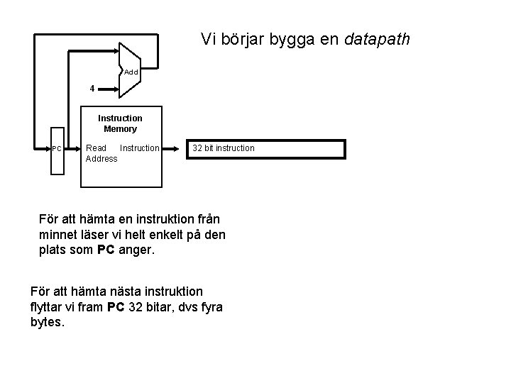
Vi börjar bygga en datapath Add 4 Instruction Memory PC Read Instruction Address 32 bit instruction För att hämta en instruktion från minnet läser vi helt enkelt på den plats som PC anger. För att hämta nästa instruktion flyttar vi fram PC 32 bitar, dvs fyra bytes.
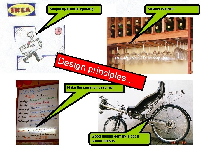
Simplicity favors regularity Desi gn p Smaller is faster rincip les. . . Make the common case fast. Good design demands good compromises
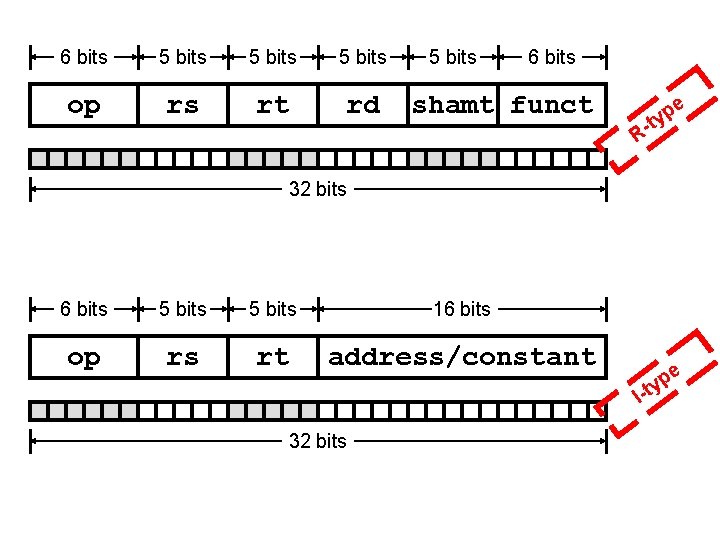
6 bits 5 bits op rs rt rd 5 bits 6 bits shamt funct e p y t R- 32 bits 6 bits 5 bits 16 bits op rs rt address/constant I-t e p y 32 bits
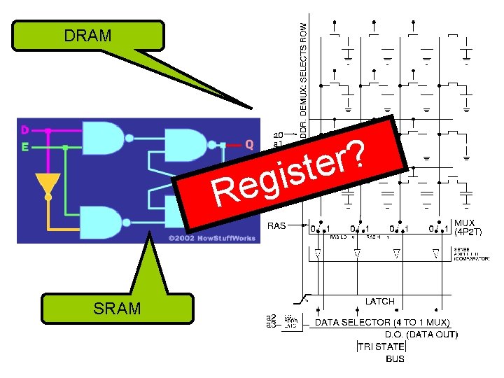
DRAM ? r e t s i g Re SRAM
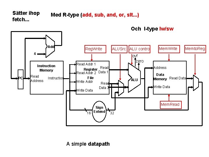
Sätter ihop fetch. . . Med R-type (add, sub, and, or, slt. . . ) Och I-type lw/sw Add Reg. Write ALUSrc ALU control 4 Instruction Memory PC Read Address Instruction Address ALU A simple datapath Data Memory Read Data Write Data 2 Sign 16 Extend Memto. Reg ovf zero Read Addr 1 Register Read Addr 2 Data 1 File Write Addr Read Write Data Mem. Write Mem. Read 32
beq $t 1, $t 2 my_label Hur funkar branchinstruktioner. . .
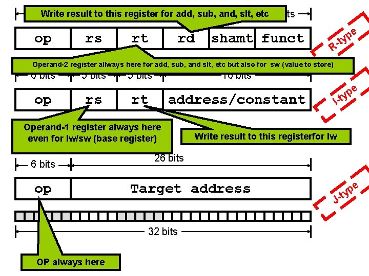
Write result to this register 6 bits 5 bits for 5 add, bitssub, and, 5 bitsslt, etc 6 bits op rs rt rd shamt funct e p y t R- Operand-2 register allways here for add, sub, and slt, etc but also for sw (value to store) 6 bits op 5 bits rs 5 bits 16 bits rt address/constant Operand-1 register always here even for lw/sw (base register) 6 bits op I Write result to this registerfor lw 26 bits Target address 32 bits OP always here e p -ty J- t e p y
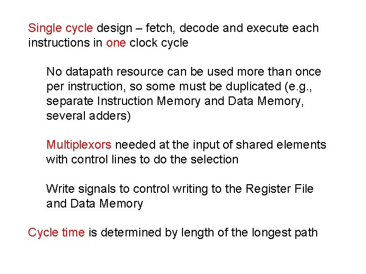
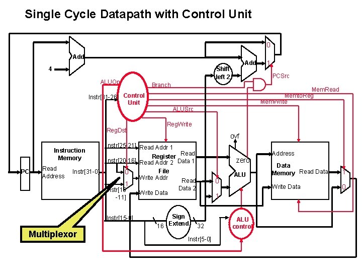
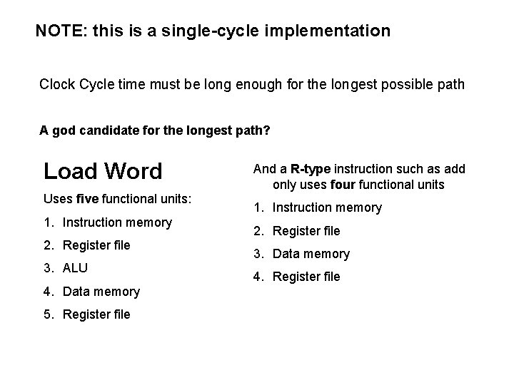
Single cycle design – fetch, decode and execute each instructions in one clock cycle No datapath resource can be used more than once per instruction, so some must be duplicated (e. g. , separate Instruction Memory and Data Memory, several adders) Multiplexors needed at the input of shared elements with control lines to do the selection Write signals to control writing to the Register File and Data Memory Cycle time is determined by length of the longest path
Single Cycle Datapath with Control Unit 0 Add ALUOp Reg. Dst PC Read Address Instr[31 -0] ALUSrc Reg. Write ovf 1 Instr[15 -0] Multiplexor Mem. Read Memto. Reg Mem. Write Instr[25 -21] Read Addr 1 Register Read Instr[20 -16] Read Addr 2 Data 1 File 0 Write Addr Read Instr[15 -11] 1 PCSrc Branch Instr[31 -26] Control Unit Instruction Memory Add Shift left 2 4 Write Data zero 0 ALU Data 2 1 Sign 16 Extend 32 Instr[5 -0] ALU control Address Data Memory Read Data 1 Write Data 0
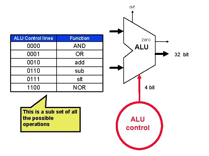
ovf ALU Control lines Function 0000 0001 0010 0111 1100 AND OR add sub slt NOR This is a sub set of all the possible operations zero ALU 32 bit 4 bit ALU control
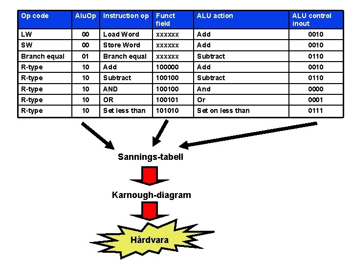
Op code Alu. Op Instruction op Funct field ALU action ALU control inout LW 00 Load Word xxxxxx Add 0010 SW 00 Store Word xxxxxx Add 0010 Branch equal 01 Branch equal xxxxxx Subtract 0110 R-type 10 Add 100000 Add 0010 R-type 10 Subtract 100100 Subtract 0110 R-type 10 AND 100100 And 0000 R-type 10 OR 100101 Or 0001 R-type 10 Set less than 101010 Set on less than 0111 Sannings-tabell Karnough-diagram Hårdvara
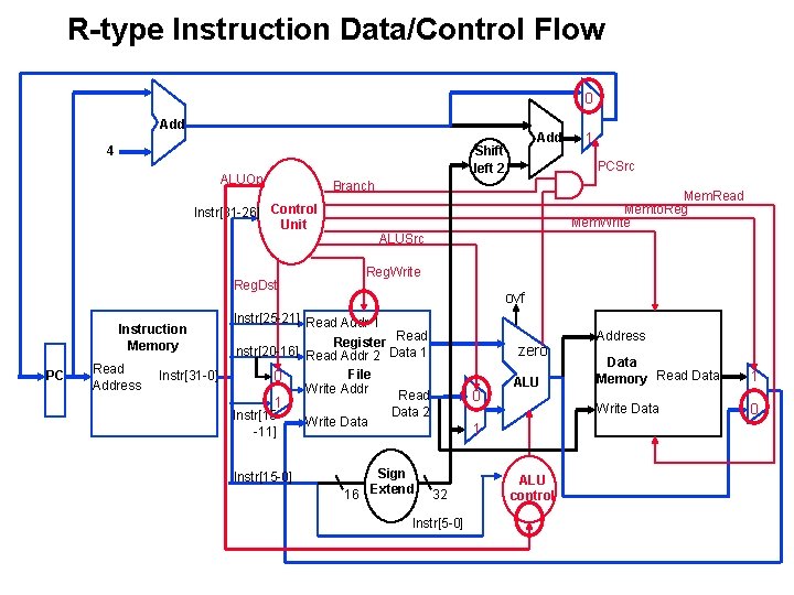
R-type Instruction Data/Control Flow 0 Add ALUOp Reg. Dst PC Read Address Instr[31 -0] Mem. Read Memto. Reg Mem. Write ALUSrc Reg. Write ovf Instr[25 -21] Read Addr 1 Register Read Instr[20 -16] Read Addr 2 Data 1 File 0 Write Addr Read 1 Instr[15 -11] Instr[15 -0] 1 PCSrc Branch Instr[31 -26] Control Unit Instruction Memory Add Shift left 2 4 Write Data zero 0 ALU Data 2 1 Sign 16 Extend 32 Instr[5 -0] ALU control Address Data Memory Read Data 1 Write Data 0
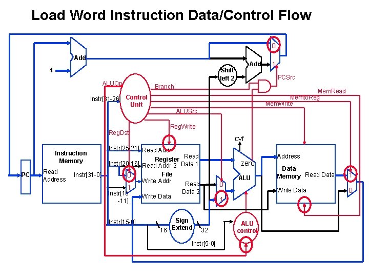
Load Word Instruction Data/Control Flow 0 Add ALUOp Reg. Dst PC Read Address Instr[31 -0] Mem. Read Memto. Reg Mem. Write ALUSrc Reg. Write ovf Instr[25 -21] Read Addr 1 Register Read Instr[20 -16] Read Addr 2 Data 1 File 0 Write Addr Read 1 Instr[15 -11] Instr[15 -0] 1 PCSrc Branch Instr[31 -26] Control Unit Instruction Memory Add Shift left 2 4 Write Data zero 0 ALU Data 2 1 Sign 16 Extend 32 Instr[5 -0] ALU control Address Data Memory Read Data 1 Write Data 0
NOTE: this is a single-cycle implementation Clock Cycle time must be long enough for the longest possible path A god candidate for the longest path? Load Word Uses five functional units: 1. Instruction memory 2. Register file 3. ALU 4. Data memory 5. Register file And a R-type instruction such as add only uses four functional units 1. Instruction memory 2. Register file 3. Data memory 4. Register file
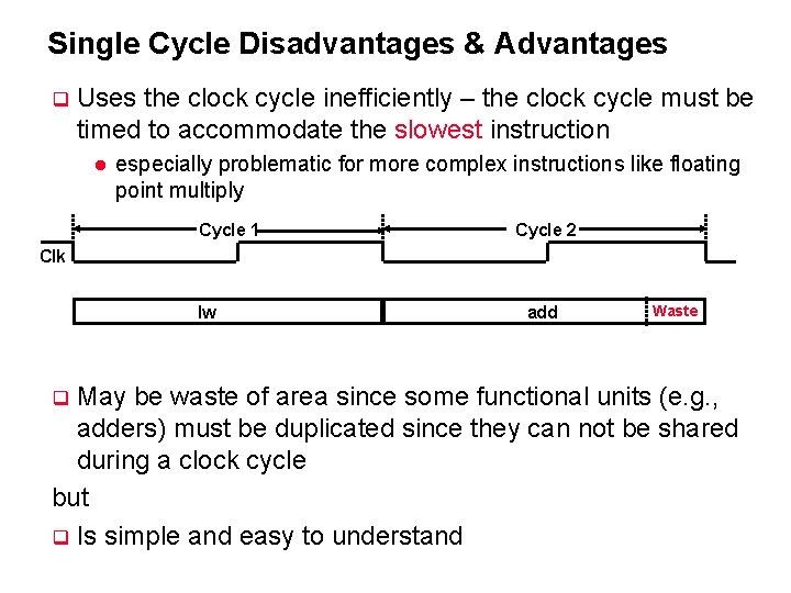
Single Cycle Disadvantages & Advantages q Uses the clock cycle inefficiently – the clock cycle must be timed to accommodate the slowest instruction l especially problematic for more complex instructions like floating point multiply Cycle 1 Cycle 2 Clk lw add Waste May be waste of area since some functional units (e. g. , adders) must be duplicated since they can not be shared during a clock cycle but q Is simple and easy to understand q
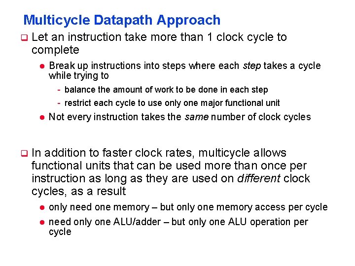
Multicycle Datapath Approach q Let an instruction take more than 1 clock cycle to complete l Break up instructions into steps where each step takes a cycle while trying to - balance the amount of work to be done in each step - restrict each cycle to use only one major functional unit l q Not every instruction takes the same number of clock cycles In addition to faster clock rates, multicycle allows functional units that can be used more than once per instruction as long as they are used on different clock cycles, as a result l l only need one memory – but only one memory access per cycle need only one ALU/adder – but only one ALU operation per cycle
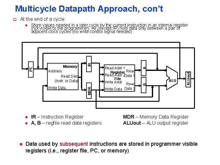
Multicycle Datapath Approach, con’t At the end of a cycle Write Data l l l IR – Instruction Register A, B – regfile read data registers ALUout Read Addr 1 Register Read Addr 2 Data 1 File Write Addr Read Write Data 2 A Address Read Data (Instr. or Data) B Memory IR Store values needed in a later cycle by the current instruction in an internal register (not visible to the programmer). All (except IR) hold data only between a pair of adjacent clock cycles (no write control signal needed) MDR l PC q MDR – Memory Data Register ALUout – ALU output register Data used by subsequent instructions are stored in programmer visible registers (i. e. , register file, PC, or memory)
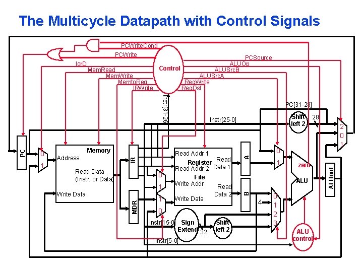
The Multicycle Datapath with Control Signals Address Read Data (Instr. or Data) 1 1 Write Data 0 Write Data Shift left 2 Instr[25 -0] Read Addr 1 Register Read Addr 2 Data 1 File Write Addr Read IR 1 Memory MDR PC Instr[31 -26] 0 PC[31 -28] Data 2 Instr[15 -0] Sign Extend 32 Instr[5 -0] Shift left 2 2 0 1 zero ALU 4 0 28 0 1 2 3 ALU control ALUout Mem. Read Mem. Write Memto. Reg IRWrite PCSource ALUOp Control ALUSrc. B ALUSrc. A Reg. Write Reg. Dst A Ior. D B PCWrite. Cond PCWrite
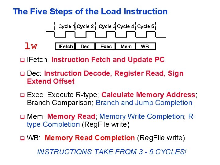
The Five Steps of the Load Instruction Cycle 1 Cycle 2 Cycle 3 Cycle 4 Cycle 5 lw IFetch Dec Exec Mem WB q IFetch: Instruction Fetch and Update PC q Dec: Instruction Decode, Register Read, Sign Extend Offset q Exec: Execute R-type; Calculate Memory Address; Branch Comparison; Branch and Jump Completion q Mem: Memory Read; Memory Write Completion; Rtype Completion (Reg. File write) q WB: Memory Read Completion (Reg. File write) INSTRUCTIONS TAKE FROM 3 - 5 CYCLES!
Hungrig!