Footing Design Types of Footing Wall footings are


 Design a combined footing As shown")


")


- Slides: 60
Footing Design
Types of Footing Wall footings are used to support structural walls that carry loads for other floors or to support nonstructural walls.
Types of Footing Isolated or single footings are used to support single columns. This is one of the most economical types of footings and is used when columns are spaced at relatively long distances.
Types of Footing Combined footings usually support two columns, or three columns not in a row. Combined footings are used when two columns are so close that single footings cannot be used or when one column is located at or near a property line.
Types of Footing Cantilever or strap footings consist of two single footings connected with a beam or a strap and support two single columns. This type replaces a combined footing and is more economical.
Types of Footing Continuous footings support a row of three or more columns. They have limited width and continue under all columns.
Types of Footing Rafted or mat foundation consists of one footing usually placed under the entire building area. They are used, when soil bearing capacity is low, column loads are heavy single footings cannot be used, piles are not used and differential settlement must be reduced.
Types of Footing Pile caps are thick slabs used to tie a group of piles together to support and transmit column loads to the piles.
Distribution of Soil Pressure When the column load P is applied on the centroid of the footing, a uniform pressure is assumed to develop on the soil surface below the footing area. However the actual distribution of the soil is not uniform, but depends on may factors especially the composition of the soil and degree of flexibility of the
Distribution of Soil Pressure Soil pressure distribution in cohesionless soil. Soil pressure distribution in cohesive soil.
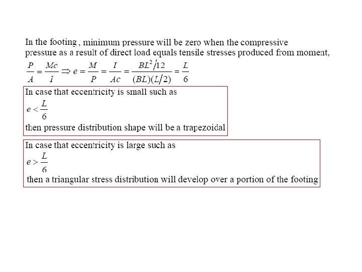
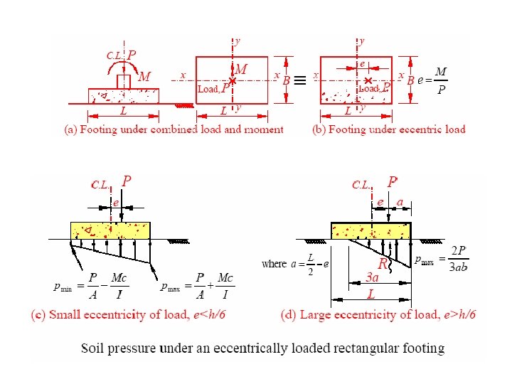
Eccentrically loaded footings
Eccentrically loaded footings Example Isolated Footing D. L = 900 k. N L. L = 450 k. N Ms = 150 k. N. m Mu=200 k. N. m qall =200 kpa M
Area required approximated 124. 7 Check stress 183. 7
Ultimate pressure under footing 245 166 245
Check Punching Shear
Check Beam Shear
3. 5 m Bending moment design Long direction 245 166 245
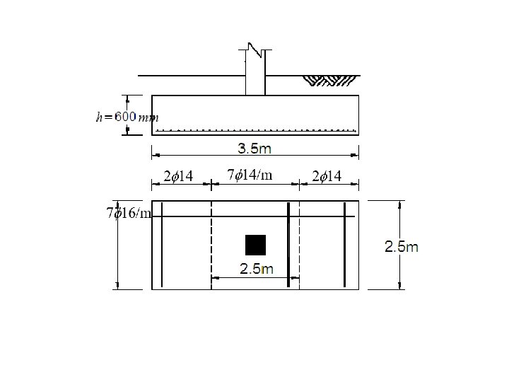
Bending moment design 2. 5 m Short direction 245 166 245
Central band ratio = Central band of short direction = 0. 83 As = 0. 83 (10. 1)=8. 6 cm 2
Footing Design Part II Combined footing
Example 1 Design a combined footing As shown
Dimension calculation The base dimension to get uniform distributed load 2000 k. N 800 k. N 1200 k. N A x 1=0. 2 m x 2=6. 2 m x 800(0. 2)+1200(6. 2)=2000(x) x = 3. 8 m 800 k. N 1200 k. N Try thickness =80 cm 2 x =7. 6 m
Area required
Check for punching Shear d = 730 mm 1. 13 m A 0. 765
B
Draw S. F. D & B. M. D Stress under footing = 190 *1. 8 = 342 k. N/m
Check for beam shear b = 1800 mm, d = 730 mm
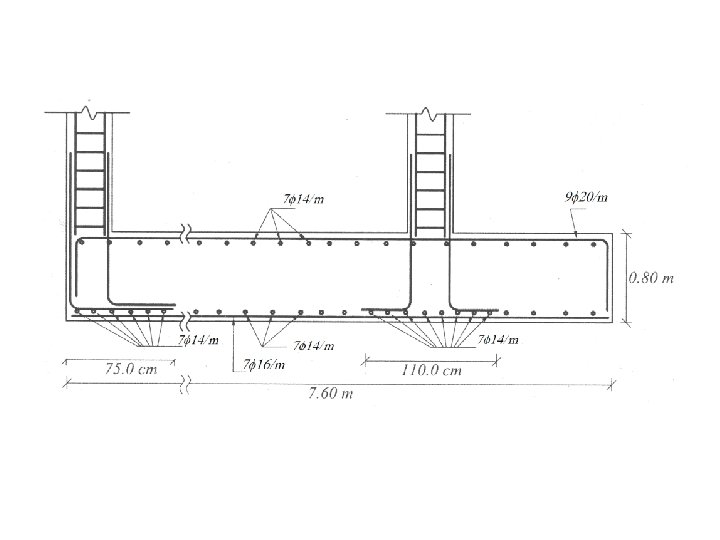
Bending moment Long direction
Bending moment Short Under Column A direction
Under Column B Shrinkage Reinforcement in short direction
Footing Design Part III Combined footing, strip footing, & Mat foundatio
Example 2 Design a combined footing As shown
Dimension calculation The base dimension to get uniform distributed load 1950 k. N 1200 k. N 750 k. N A x 1=0. 2 m x 2=4. 2 m x 750(4. 2)+1200(0. 2)=1950 (x) x = 1. 75 m
Area required
Check for punching Shear h= 750 mm d = 732 mm A B 2=1 m B 1=4 m
B
Draw S. F. D & B. M. D
Empirical S. F. D & B. M. D m Convert trapezoidal load to rectangle Mmax Clear distance between column B in moment design = ave. width = 2. 5 m
Check for beam shear d = 665 mm b Y=1. 5 m x 4 m 1 m
Bending moment Long Top Bottom direction
Bending moment Short Under Column A direction
Under Column B Shrinkage Reinforcement in short direction
Reinforcement details
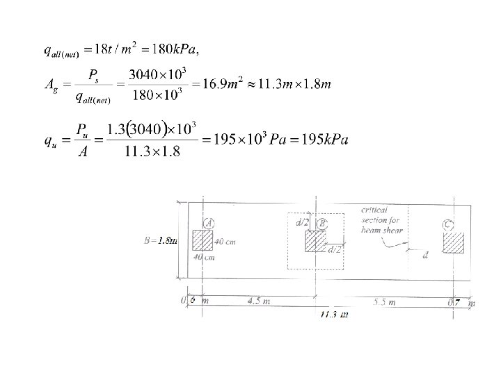
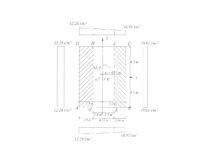
Example 3 (Strip footing) Design a combined footing As shown
Dimension calculation The base dimension to get uniform distributed load 3040 k. N 800 k. N 1280 k. N 960 k. N A Assume L 1=0. 6 x 1=5. 2 m x 2=10. 7 m x 800(0. 6)+1280(5. 1)+960(10. 6)= 3040 (x) x = 5. 65 m, 2(x)=11. 3 m L 2=11. 3 - (10. 6)=0. 7 L 2
Check for punching Shear h = 700 mm d=630 mm Example B You can check other columns
Draw S. F. D & B. M. D Stress under footing = 195 *1. 8 = 351 k. N/m
Check for beam shear b = 1800 mm, d = 630 mm
Bending moment Long Design Short direction as example 1 (lecture 11)
Reinforcement details
Mat Foundation
Check for punching Shear
General Example, Ref. 2 Modified load
General reinforcement details