Fire Safety Engineering Structures in Fire Workshop at


- Slides: 50
Fire Safety Engineering & Structures in Fire Workshop at Indian Institute of Science 9 -13 August, 2010 Bangalore India Fire Safety Engineering Methods Session JT 10 Organisers: CS Manohar and Ananth Ramaswamy Indian Institute of Science Speakers: Jose Torero, Asif Usmani and Martin Gillie The University of Edinburgh Funding and Sponsorship:
Suppression § Water Suppression
Should Active Suppression be Used? § Why can the decision of not using active suppression be made? § § Cost Environmental Concerns Damage of Property Incompatibility with the purpose of the building § Fire is a complex problem that requires a “cost/benefit” analysis
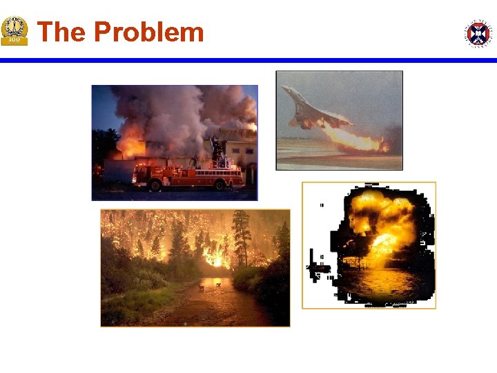
The Problem
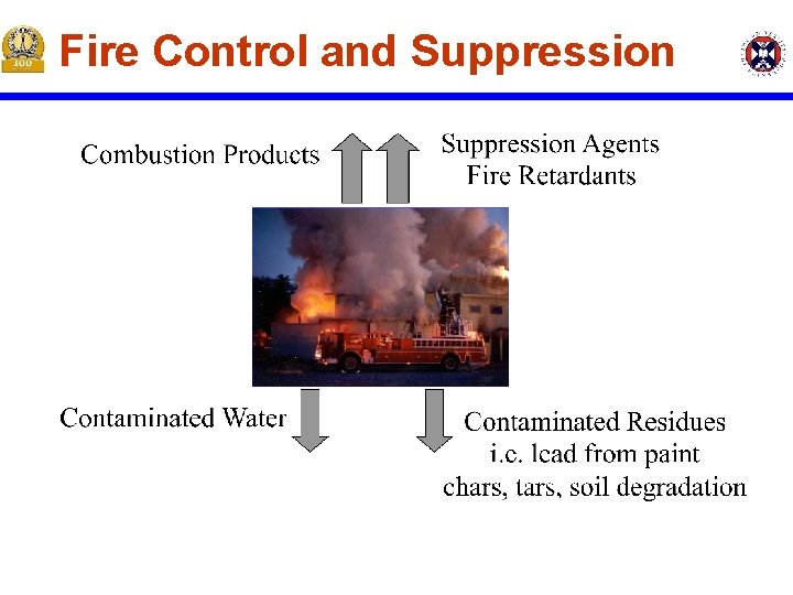
Fire Control and Suppression
Fire Prevention § Early Detection § Smoke Detectors, CO Detectors, IR Detectors, UV Detectors, Motion Detectors § Effective but not infallible § Proper Material Selection § Low Flammability Materials - not always possible to use – many times are not cost effective § Fuels – aircraft, cars, ships § Plastics – everyday use § Metals – flammable under extreme conditions – i. e. turbine engines
Fire Retardants § Additives used to reduce the “flammability” of a material § Halogen-based retarded materials – i. e. PVC § Inhibit gas phase combustion chemistry § Produce contaminants during a fire § Produce contaminants during recycling § Phosphorous based charring materials § § Formation of chars – reduces flow of fuel to flame Produce contaminants during fire Contaminate suppression water Lead to smolder fires – very difficult to detect and suppress § New environmentally friendly technologies § Based on carbon fibers and nano-composites – still under development
Fire Suppression § § § Water Sprinklers Water Mists Gaseous Agents Foams Dry Chemicals
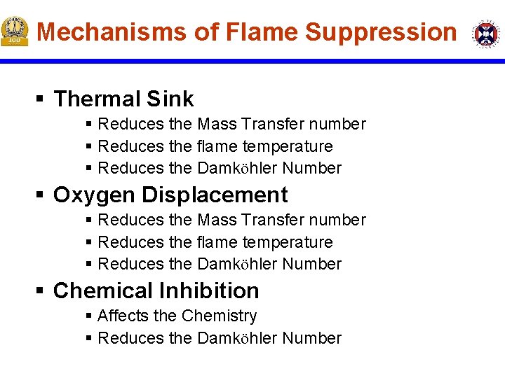
Mechanisms of Flame Suppression § Thermal Sink § Reduces the Mass Transfer number § Reduces the flame temperature § Reduces the Damköhler Number § Oxygen Displacement § Reduces the Mass Transfer number § Reduces the flame temperature § Reduces the Damköhler Number § Chemical Inhibition § Affects the Chemistry § Reduces the Damköhler Number
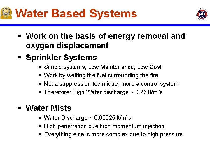
Water Based Systems § Work on the basis of energy removal and oxygen displacement § Sprinkler Systems § § Simple systems, Low Maintenance, Low Cost Work by wetting the fuel surrounding the fire Not a suppression technique, more a control system Therefore: High Water discharge ~ 0. 25 lt/m 2 s § Water Mists § Water Discharge ~ 0. 00025 lt/m 2 s § High penetration due high momentum injection § Everything else is more complex due to high pressure
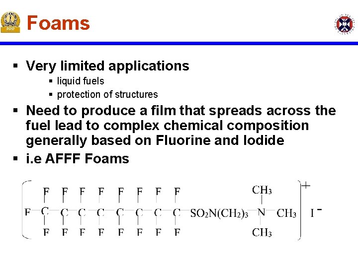
Foams § Very limited applications § liquid fuels § protection of structures § Need to produce a film that spreads across the fuel lead to complex chemical composition generally based on Fluorine and Iodide § i. e AFFF Foams
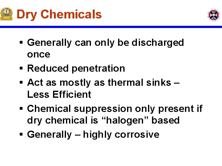
Dry Chemicals § Generally can only be discharged once § Reduced penetration § Act as mostly as thermal sinks – Less Efficient § Chemical suppression only present if dry chemical is “halogen” based § Generally – highly corrosive
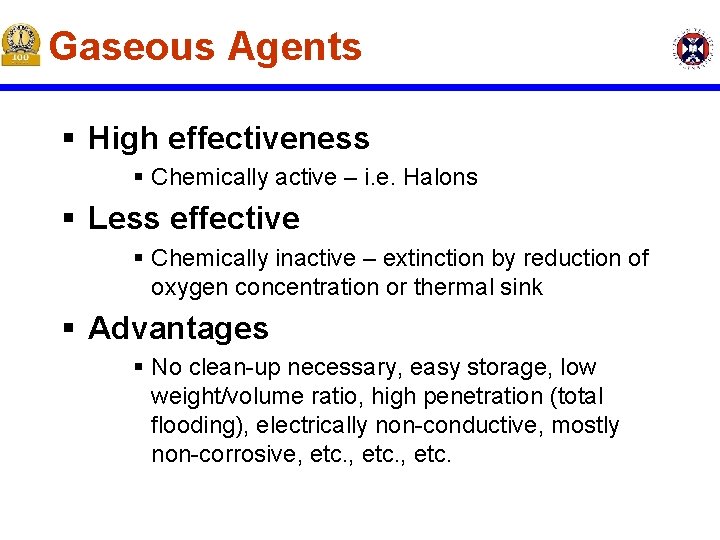
Gaseous Agents § High effectiveness § Chemically active – i. e. Halons § Less effective § Chemically inactive – extinction by reduction of oxygen concentration or thermal sink § Advantages § No clean-up necessary, easy storage, low weight/volume ratio, high penetration (total flooding), electrically non-conductive, mostly non-corrosive, etc.
Mechanisms of Flame Suppression § Most effective is Chemical Inhibition § Halons are extremely effective at attacking “chain branching” reactions in combustion processes
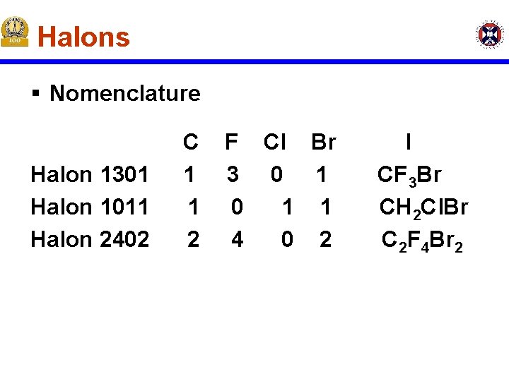
Halons § Nomenclature Halon 1301 Halon 1011 Halon 2402 C 1 1 2 F Cl Br 3 0 1 1 4 0 2 I CF 3 Br CH 2 Cl. Br C 2 F 4 Br 2
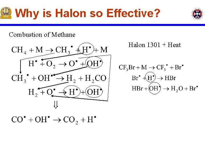
Why is Halon so Effective? Combustion of Methane Halon 1301 + Heat
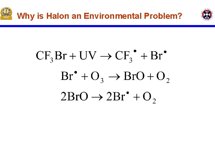
Why is Halon an Environmental Problem?
Consequences § The Montreal protocol banned the manufacturing and use of Halon 1301 § No other alternative has proven to be as effective as Halon 1301 Fact § Halon is present in 98% of commercial aircraft § In 2000 there where 178 Halon discharges in commercial aircraft § It has been estimated that of those 178 discharges more than 100 would have resulted in generalized fires that would have crashedlanded the aircraft
Conclusion § § Is it justifiable to ban the use of Halon 1301 for fire applications? Is environmental protection a sufficient “cost” to overwhelm the “benefits” of Halon 1301? Fact § The ozone depleting potential of all fire related Halon 1301 deployments in a year is equivalent to that of the emissions of 132 cars!
Water Suppression-Sprinkler Systems § Water suppression is the most commonly used mechanism of active fire control in structures § Among the different water suppression systems, sprinklers are by far the most commonly used § Some design considerations will be presented
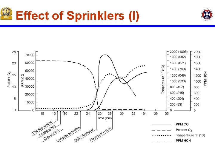
Effect of Sprinklers (I)
Effect of Sprinklers (II) § Increase the time to “Flash-Over” § Decrease toxic product concentrations, CO, HCN, etc. § Decrease the room temperature § Push the hot layer down slowing fire growth § Increase visibility “soot” dissolves in water
Effect of Sprinklers (III) § “sprinklers” are NOT designed to Extinguish the fire § “sprinklers” are designed to Increase the time available to extinguish the fire
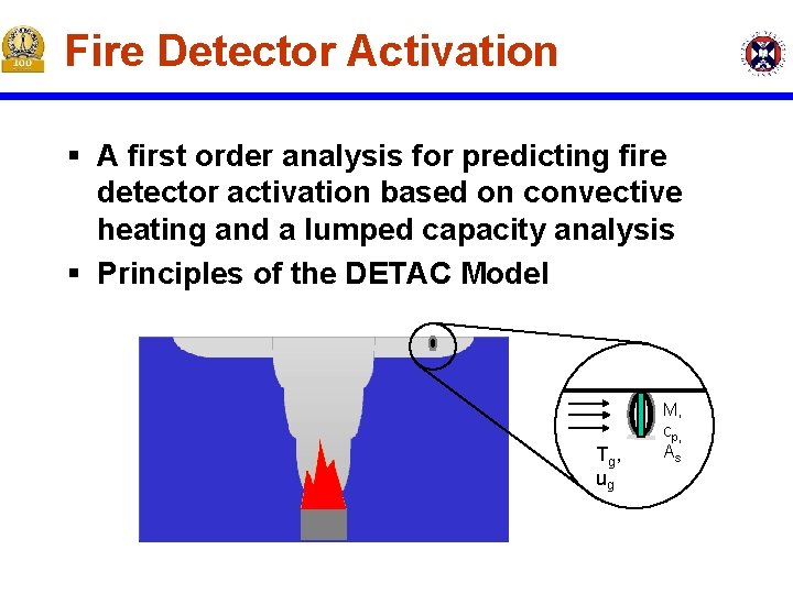
Fire Detector Activation § A first order analysis for predicting fire detector activation based on convective heating and a lumped capacity analysis § Principles of the DETAC Model Tg , ug M, cp, As
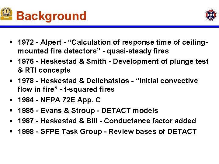
Background § 1972 - Alpert - “Calculation of response time of ceilingmounted fire detectors” - quasi-steady fires § 1976 - Heskestad & Smith - Development of plunge test & RTI concepts § 1978 - Heskestad & Delichatsios - “Initial convective flow in fire” - t-squared fires § 1984 - NFPA 72 E App. C § 1985 - Evans & Stroup - DETACT models § 1987 - Heskestad & Bill - Conductance factor added § 1998 - SFPE Task Group - Review bases of DETACT
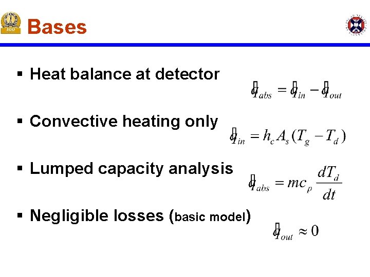
Bases § Heat balance at detector § Convective heating only § Lumped capacity analysis § Negligible losses (basic model)
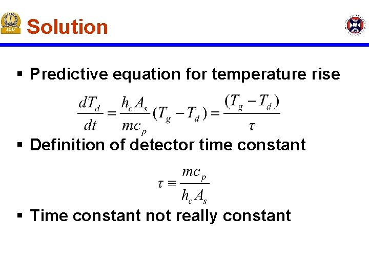
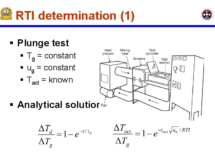
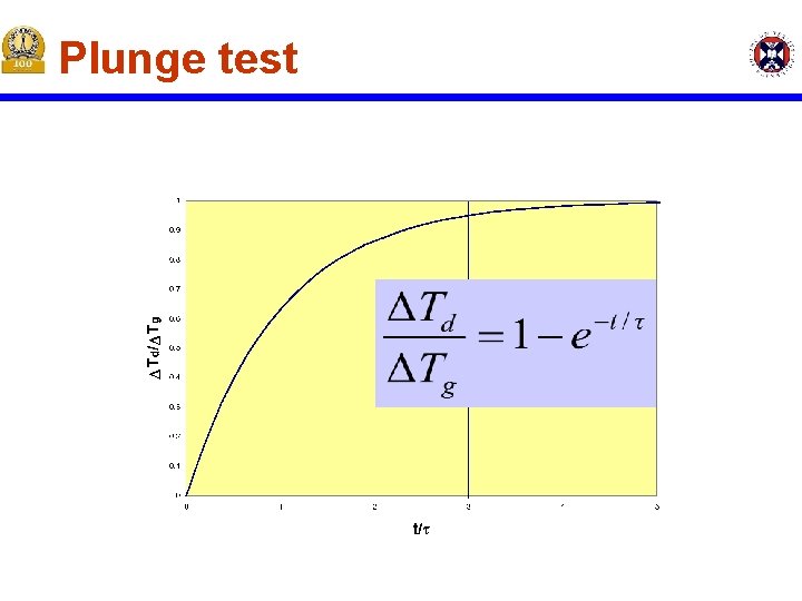
Solution § Predictive equation for temperature rise § Definition of detector time constant § Time constant not really constant
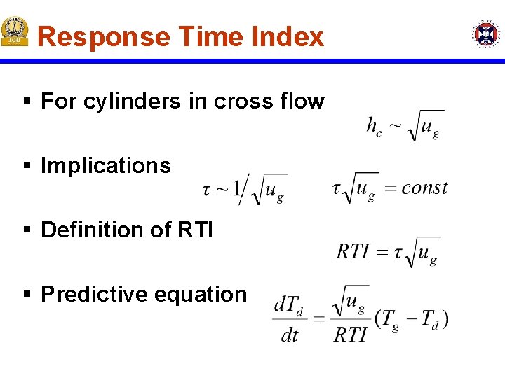
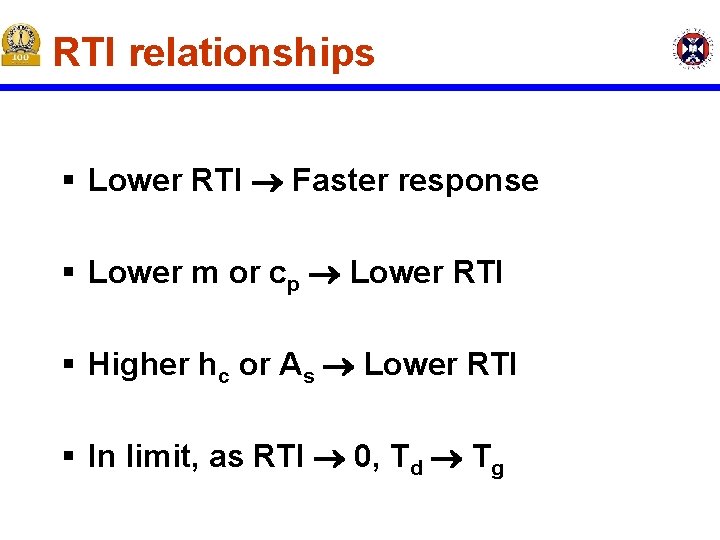
Response Time Index § For cylinders in cross flow § Implications § Definition of RTI § Predictive equation
RTI relationships § Lower RTI Faster response § Lower m or cp Lower RTI § Higher hc or As Lower RTI § In limit, as RTI 0, Td Tg
RTI determination (1) § Plunge test § Tg = constant § ug = constant § Tact = known § Analytical solution
Plunge test
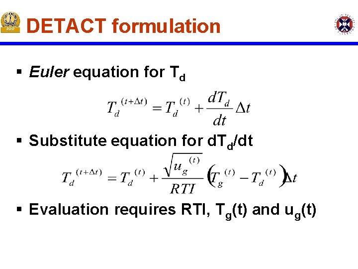
DETACT formulation § Euler equation for Td § Substitute equation for d. Td/dt § Evaluation requires RTI, Tg(t) and ug(t)
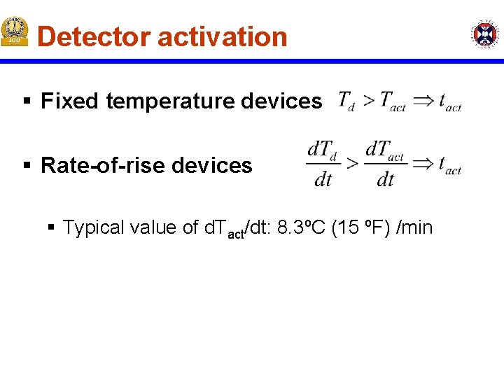
Detector activation § Fixed temperature devices § Rate-of-rise devices § Typical value of d. Tact/dt: 8. 3ºC (15 ºF) /min
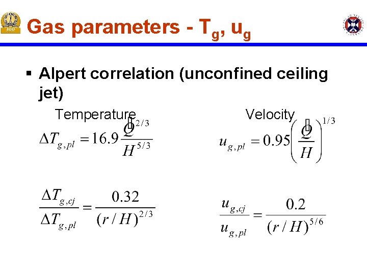
Gas parameters - Tg, ug § Alpert correlation (unconfined ceiling jet) Temperature Velocity
General Information § Based on NFPA 13 – National Fire Protection Association Codes § Sprinkler selection is based on the rapidity with which thermal sensor operates - RTI
Sprinkler System Design § The design of a sprinkler system consists of the following steps: § § § Identification of the fuel load Identification of the use of the building Calculation of the sprinkler density Determination of sprinkler placement Definition of the different components of the system § § Sprinklers Pipes Pumps Valves § Establishment of maintenance procedures
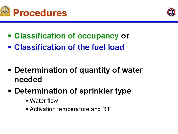
Procedures § Classification of occupancy or § Classification of the fuel load § Determination of quantity of water needed § Determination of sprinkler type § Water flow § Activation temperature and RTI
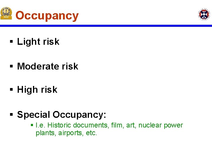
Occupancy § Light risk § Moderate risk § High risk § Special Occupancy: § I. e. Historic documents, film, art, nuclear power plants, airports, etc.
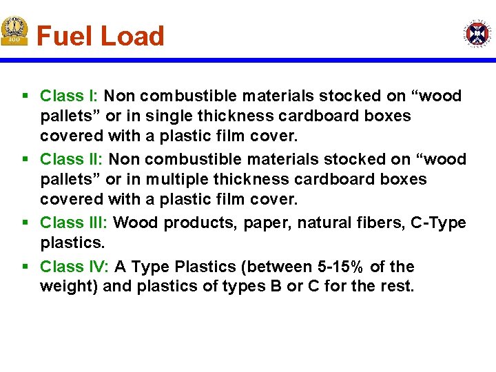
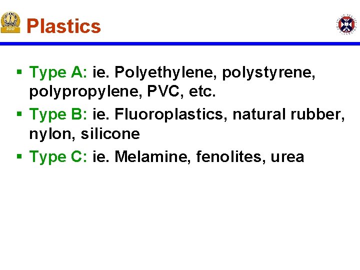
Fuel Load § Class I: Non combustible materials stocked on “wood pallets” or in single thickness cardboard boxes covered with a plastic film cover. § Class II: Non combustible materials stocked on “wood pallets” or in multiple thickness cardboard boxes covered with a plastic film cover. § Class III: Wood products, paper, natural fibers, C-Type plastics. § Class IV: A Type Plastics (between 5 -15% of the weight) and plastics of types B or C for the rest.
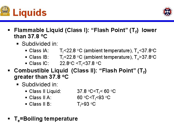
Liquids § Flammable Liquid (Class I): “Flash Point” (Tf) lower than 37. 8 o. C § Subdivided in: § Class IA: § Class IB: § Class IC: Tf<22. 8 o. C (ambient temperature), Te<37. 8 o. C Tf<22. 8 o. C (ambient temperature), Te>37. 8 o. C 22. 8 o. C <Tf<37. 8 o. C § Combustible Liquid (Class II): “Flash Point” (Tf) greater than 37. 8 o. C § Subdivided in: § Class II Liquid: § Class II A: § Class II B: 37. 8 o. C<Tf< 60 o. C<Tf<93 o. C Tf>93 o. C § Te=Boiling temperature
Plastics § Type A: ie. Polyethylene, polystyrene, polypropylene, PVC, etc. § Type B: ie. Fluoroplastics, natural rubber, nylon, silicone § Type C: ie. Melamine, fenolites, urea
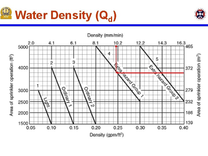
Water Density (Qd)
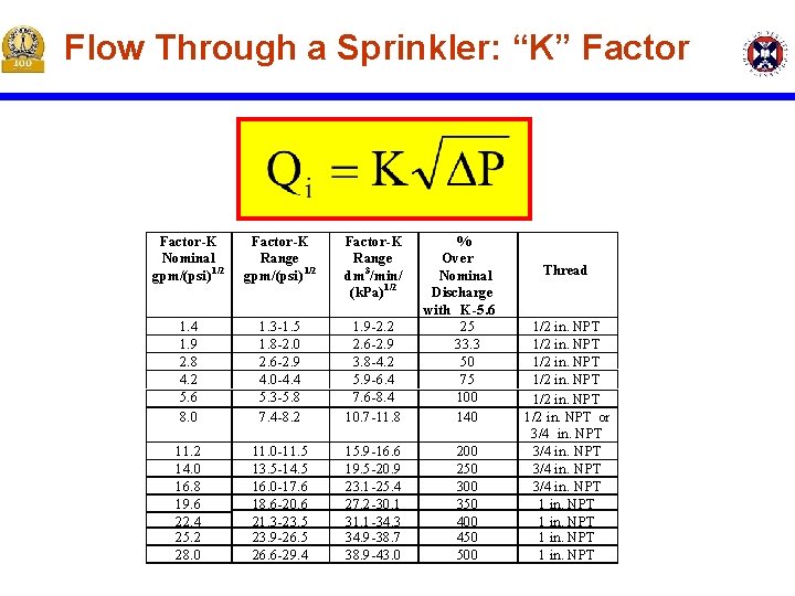
Flow Through a Sprinkler: “K” Factor-K Nominal gpm/(psi) 1/2 Factor-K Range dm 3/min/ (k. Pa) 1/2 1. 4 1. 9 2. 8 4. 2 5. 6 8. 0 1. 3 -1. 5 1. 8 -2. 0 2. 6 -2. 9 4. 0 -4. 4 5. 3 -5. 8 7. 4 -8. 2 1. 9 -2. 2 2. 6 -2. 9 3. 8 -4. 2 5. 9 -6. 4 7. 6 -8. 4 10. 7 -11. 8 11. 2 14. 0 16. 8 19. 6 22. 4 25. 2 28. 0 11. 0 -11. 5 13. 5 -14. 5 16. 0 -17. 6 18. 6 -20. 6 21. 3 -23. 5 23. 9 -26. 5 26. 6 -29. 4 15. 9 -16. 6 19. 5 -20. 9 23. 1 -25. 4 27. 2 -30. 1 31. 1 -34. 3 34. 9 -38. 7 38. 9 -43. 0 % Over Nominal Discharge with K-5. 6 25 33. 3 50 75 100 140 200 250 300 350 400 450 500 Thread 1/2 in. NPT or 3/4 in. NPT 1 in. NPT
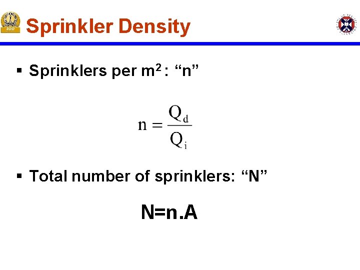
Sprinkler Density § Sprinklers per m 2 : “n” § Total number of sprinklers: “N” N=n. A
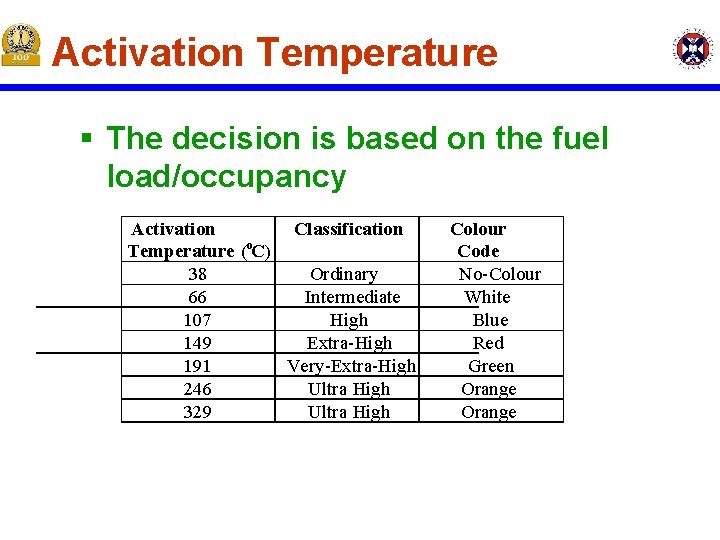
Activation Temperature § The decision is based on the fuel load/occupancy Activation Classification Temperature (o. C) 38 Ordinary 66 Intermediate 107 High 149 Extra-High 191 Very-Extra-High 246 Ultra High 329 Ultra High Colour Code No-Colour White Blue Red Green Orange
Distribution and Installation § Sprinklers are distributed through the protected space homogeneously § The water pressure will be established by the code and the sprinkler density § Water pumps are many times necessary § The total flow is established on the basis of the number of sprinklers
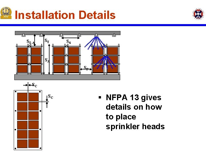
Installation Details ST-A ST SS SA SP SC SC § NFPA 13 gives details on how to place sprinkler heads
Special Sprinkler Types § Regular Sprinklers: Direct 40 -60% of the water towards the fire § § § § ESFR-Early suppression fast response Extended Coverage Large Drop Sprinkler Open Sprinklers (no actuator) Quick Response (QR) Quick Response Early Suppression (QRES) Residential Sprinklers (fast response sprinklers rated for residential use), etc. ,
Installation Types § Wet Pipe System-Standard, water filled pipes with sensor at the sprinkler head § Circulating-Closed Loop System-combined wet pipe sprinkler system with HVAC system § Dry Pipe System-Pressurized air/nitrogen, its release opens the water valve-for non-heated environments § Combined-Dry Pipe Pre-reaction System-thermal sensor + fire detection system, for fast or screened response § Deluge System-Dry pipes with a fire sensor, no thermal sensor (open sprinklers)
Limitations of this approach § Effectiveness of the system is base on empirical data for a reduced number of configurations § No quantitative estimate of the “probability of success” can be stated § No quantitative estimate of the potential “outcome” can be specified § This approach is being phased-out by performance design….