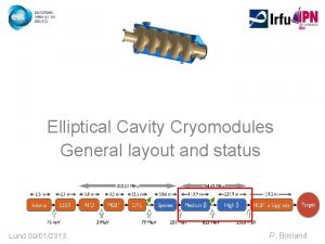
ESS elliptical cryomodules Two families of elliptical cavities


- Slides: 28

ESS elliptical cryomodules Two families of elliptical cavities: Medium beta: b=0, 67 High beta: b=0, 86 (geometrical beta values) Same cryostat for both types of cavities P. Bosland (on behalf of the CEA/Irfu and CNRS/IPNO teams) Requirements Conformance for SRF cryomodules 15 -16 October 2014 Lund 1

Cryomodule sub-system § Segmented LINAC: § Independent cryogenic cooling and control § Warm-up of a individual cryostat is possible § Individually removable cryostats for repair is possible § Focusing elements at warm temperature Requirements Conformance for SRF cryomodules 15 -16 October 2014 Lund 2

Two prototype cryomodules § M-ECCTD with medium beta cavities - 2012 – 2016 Ø FR-SW agreement Ø Collaboration IPNO and IRFU § H-ECCTD with high beta cavities - 2014 – 2017 Ø French In-kind contribution The IRFU - IPNO collaboration CEA SACLAY: “cavity package”, the cryomodule assembly and RF power tests § § § § Cavities + helium tank Power coupler design, manufacturing, RF tests Piezo tuner Magnetic shield Tooling: field flatness, cavity preparation, cryomodule assembling, … Cryomodule assembly Tests stand for cryogenic and RF power tests Tests of the ECCTD cryomodule Requirements Conformance for SRF cryomodules 15 -16 October 2014 Lund IPN ORSAY: cryostat design and fabrication § § § Vacuum vessel Space frame – cavity supports Thermal screen Superinsulation Internal cryogenic pipes Instrumentation 3

Cryomodule Design § Similar to CEBAF/SNS cryomodule with 4 cavities per cryomodule § Common design for medium (6 cells) and high beta (5 cells) cavity cryomodules § Accelerating gradient: for b=0. 67 (Medium Beta): Eacc=16. 7 MV/m Qo> 5 E 9 at 2 K for b=0. 86 (High Beta): Eacc=19. 9 MV/m Qo> 5 E 9 at 2 K • total length: 6. 6 m • Beam height: 1. 5 m § Maximum operating helium pressure: 1. 431 bar Requirements Conformance for SRF cryomodules 15 -16 October 2014 Lund 4

Medium / High beta cavity Tank (Ti) Magnetic shielding High beta (0, 86): 5 cells Length 1316, 91 mm Cold tuning system Medium beta (0, 67): 6 cells Length 1259, 40 mm Medium High 94 120 1. 22 1. 8 0. 54 1. 2 2. 36 2. 2 Bpk/Eacc (m. T/(MV/m)) 4. 79 4. 3 Maximum. r/Q (W) 394 477 Optimum b 0. 705 0. 92 G (W) 196. 63 241 Iris diameter (mm) Cell to cell coupling k (%) p and 5 p/6 (or 4 p/5) mode separation (MHz) Epk/Eacc Geometrical beta Frequency (MHz) Operating temperature (K) Maximum surface field in operation (MV/m) Nominal Accelerating gradient (MV/m) 57, 5 mm Nominal Accelerating Voltage (MV) Q 0 at nominal gradient Cavity dynamic heat load (W) Qext Medium High 0. 67 0. 86 704. 42 2 44 44 16. 7 19. 9 14, 3 18, 2 > 5 e 9 4, 9 7. 5 105 6, 5 7. 6 105 No HOM couplers HOM frequencies must be carefully controlled Requirements Conformance for SRF cryomodules 15 -16 October 2014 Lund 5

Fundamental power coupler Pmax = 1. 2 MW peak at 4 % duty cycle → critical component Ø RF ceramic window Ø Inner conductor • Conical tip for stronger coupling • Water cooling Ø Outer conductor • Cooled with Liquid He in the vac. Vessel Ø Coax to rectangular RF transition (Door Knob) • HV bias with RF trap Ø CM integration • Large diameter flange with below on vacuum vessel • Diagnostic ports distribution Coupler conditioning set-up Requirements Conformance for SRF cryomodules 15 -16 October 2014 Lund 6

Supports of the different cold components • Blocking nut Cross rods fixed on 2 titanium half rings fastened to the helium tank on Pre-stress nut one side and on the spaceframe on Rods (TA 6 V, Diam. 6 mm) Magnetic shield Half rings linked to the tank (under the magnetic shield) the other side • 3000 N pre-stress applied on the rods, maximum force 8500 N per rod after cooling down Rod Thermal shield 3 jacks at 120° supporting the spaceframe after insertion Supporting rods • 2 wheels fixed to the spaceframe at each extremity • Guiding ensured by two rails welded to the vacuum vessel • Requirements Conformance for SRF cryomodules 15 -16 October 2014 Special boxes allowing the axial moving and the Lund thermalization of thermal shield 7

Inter-cavities bellows Mechanical cavity misalignment on the cavity strings Longitudinal shrinkage of the cavities Thermal isolation at the two extremities of the cryomodule MEDIUM BETA Number of corrugations: 10 Overall length 240, 5 mm Axial stiffness for 10 corrugations 21 N/mm Radial stroke for 10 corrugations +/-0. 80 mm Radial stiffness for 10 corrugations 4450 N/mm Cold to warm transition HIGH BETA Number of corrugations: 6 Overall length 183 mm (at rest) Axial stiffness for 6 corrugations 35 N/mm Radial stroke for 6 corrugations +/-0. 48 mm Radial stiffness for 6 corrugations 7417 N/mm Distribution of the RF HOM modes Requirements Conformance for SRF cryomodules 15 -16 October 2014 Lund 8

Spaceframe Forces on Rods: 3000 to 9000 N Mass spaceframe: 400 - 430 Kg Total mass of cavities + thermal shielding: 1200 Kg Blocking by 3 jacks on two levels Tuning (3 positions) Spaceframe: • Aluminium alloy • Lower part can be disassembled to insert the couplers Depl. Total (mm) Depl. Struct. (mm) Depl. Blocs (mm) 1, 32 1, 24 0, 12 à 1, 08 (Z: -1, 21 à +0, 50) (Z: -0, 89 à +0, 18) Requirements Conformance for SRF cryomodules 15 -16 October 2014 Lund Contrainte max (Mpa) 30 9

Access traps § blocking of the cavities and spaceframe during transport § Access in the tunnel § Maintenance of cold tuning system (change motor and piezo) Requirements Conformance for SRF cryomodules 15 -16 October 2014 Lund 10

Alignement of the cavities 1 3 Beam axis reported to reflector bracket on beam flanges Vessel alignment with respect to cavity string 2 Alignment of the cavity string within 1, 5 mm of the beam axis 4 Reflector brackets (vessel alignment) Alignment made by laser tracker Alignment of the cryomodule in the tunnel (source ESS) Reflector brackets (coupler flange) Reflector brackets (cavity flange) Additional fiducials will be set up inside the ECCTD cryomodule to check the alignment after cooling down. Requirements Conformance for SRF cryomodules 15 -16 October 2014 1, 5" Corner cube reflector Lund 11

Heat loads Values in Watts Requirements Conformance for SRF cryomodules 15 -16 October 2014 Lund 12

Helium cooling PID • Special boxes allowing the axial moving and thermalization of thermal shield Requirements Conformance for SRF cryomodules 15 -16 October 2014 Lund 13

Compliance with the PED 97/23/EC Relative pressure Vessels 1 bar Pipes Elliptical cavity 50 L PS<0, 5 bar: The equipment is not on the scope of the 97/23/CE directive Article 3. 3 The equipment must be designed and manufactured according to workmanlike way Category I The manufacturing must be more documented, especially with internal production control § Objective: stay within « Article 3. 3 » area Requirements Conformance for SRF cryomodules 15 -16 October 2014 Lund 14

Helium Pressure relief devices Cavity pressure test 1, 43 PS Absolute pressure 1, 9 bar PS European rules compliance Article 3. 3 1, 431 bar (1, 3 +10%) 1, 301 bar WP Maximum allowable overpressure PS + 10% SAFETY DEVICES 2, 72 bar 2, 09 bar Bursting disks +/- 10% PSET + 10% Max. allowable press. 1, 891 bar 1, 81 bar PSET Set Pressure BURSTING DISK PSET – 10% 1, 729 bar Safety margin 59 mbar (overpressure when opening) PMAX APERTURE = + 10 % POPENING = + 5 % PSET MAWP 1, 58 bar PSET PCLOSING = - 5 % PSET PMIN CLOSING = - 10 % PCLOSING (hysteresis before closing) Bursting area 1, 670 bar 1, 609 bar RELIEF VALVE Opening area 1, 551 bar 1, 496 bar Safety margin 65 mbar WP upper limit Working pressure = nominal pressure Requirements Conformance for SRF cryomodules 15 -16 October 2014 ESS Helium factory, circuits and operating modes Lund 15

Helium low pressure circuit 2 bursting disk at each tip + upstream safety relief valve (with he guard) To valve box A 36° angle is set up for the tank nozzle in order to allow the insertion of the cavity string and the cooling circuit inside the spaceframe Heat exchanger The circuit is designed to reduce as low as possible the overpressure in case of beam vacuum failure by using a continuous DN 100 diameter for the diphasic pipe, large curvatures and 2 DN 100 bursting disks at each extremity. 36° Worst scenario: beam vacuum failure 38 KW/m 2 heat load on the cavity wall Accidental overpressure: 230 mbar after rupture of the disks Requirements Conformance for SRF cryomodules 15 -16 October 2014 Lund 16

Status of the M-ECCTD § Cavities: § Design finished § Medium beta: fabrication started (KO meeting 03/09/2014) § Couplers: § RF window and antenna ordered § Call for tender for outer conductor (double wall) and door-knob to be launched in the following weeks § Tuners, magnetic shielding: § Design 95% finalized § Fabrication to be launched § Spaceframe, vacuum vessel: § Design finalized. Preparation of the procurement procedures in progress (goal: launch the procurement before the end of January 2015) § Test stand: modification of the cryogenic line and HV modulator in progress § Clean room assembly toolings: studies started - still in progress Requirements Conformance for SRF cryomodules 15 -16 October 2014 Lund 17

2 prototype high beta cavities haut béta have been tested: The 2 cavités ZANON et RI are within the ESS specifications. 18 Requirements Conformance for SRF cryomodules 15 -16 October 2014 Lund 18

Cryomodule assembly ESS cryomodules Workshop 15 -16 October 2014 Lund 19

M-ECCTD Two objectives: 1. To qualify the technology Assembly procedure Integration tools Items manufacturing ECCTD integration Documentation Others Final Version Preliminary Version Requirements Conformance for SRF cryomodules 15 -16 October 2014 Lund Ready for the serial cryomodules 2. To prepare the assembly procedures, the tools and the documentation for the serial elliptical cavity cryomodules 20

Analyse of the assembling sequence Student: Amaury Martin 09/2013 – 01/2014 q Study of the assembling sequence and needs of toolings Assembling in clean room Assembling outside clean room q Pre-study of the toolings: compatible with both types of cavities medium and high beta Requirements Conformance for SRF cryomodules 15 -16 October 2014 Lund 21

Coupler / cavity assembly q State of the art: interface coupler / cavity parallel to the laminar air flow Ø Horizontal coupler Ø Rotation needed after assembly to get to the final vertical position of the coupler in the cryomodule Ø Complex tooling q First rough analysis of the air flow around the flange: the air flow may be pertubated because of the reinforcement sheets of the helium tank q Choice: vertical assembly Tooling compatible for both types of cavities § Adjustment of the coupler position relative to the cavity flange Coupler horizontal Coupler vertical § Requirements for SRF cryomodules 15 -16 October 2014 Air. Conformance speed Whirlwind Lund 22

Frame and supports for the assembly in clean room Requirements Conformance for SRF cryomodules 15 -16 October 2014 Lund 23

Cavity string assembly in clean room q Design still in progress clean the from mm 1150 height: q axis. Beam room ground q Individual position adjustment system of each cavity and bellow q Supports of the cold to warm transition bellows to be designed Requirements Conformance for SRF cryomodules 15 -16 October 2014 Lund 24

Assembly outside clean room Thermal screen installed but not shown • Wheels on the spaceframe • Guiding rail on the vacuum tank Requirements Conformance for SRF cryomodules 15 -16 October 2014 Lund 25

Conclusion The implementation of the assembling process at Saclay will be based on the SPIRAL 2 and XFEL experience . Courtesy of Spiral 2 CEA team Courtesy of Catherine MADEC - XFEL Requirements Conformance for SRF cryomodules 15 -16 October 2014 Lund 26

Requirements Conformance for SRF cryomodules 15 -16 October 2014 Lund 27

Thank you for your attention Requirements Conformance for SRF cryomodules 15 -16 October 2014 Lund 28
 Little families
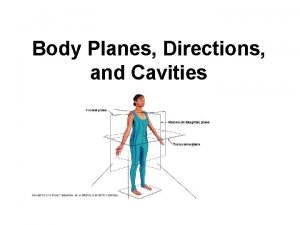
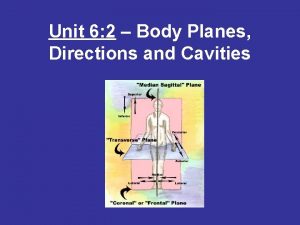
 Body planes and directions
 Jhuma biswas homeopathy
 Dressed to the
 The anterior and posterior body cavities
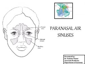
 Air containing cavities in the bones around the nose
 Abdominopelvic regions
 Body cavity
 Body cavities labeled
 Hands at sides
 Muscular process of arytenoid cartilage
 Cavo surface angle
 Echinodermata body cavity
 7.2 body planes directions and cavities
 What are the three main types of body membranes
 The brain contains four lined cavities called
 Umbilical regions
 Body quadrants
 Medial plane
 Body cavities
 Major body cavities
 Supine palm
 Animal body cavities
 Ventral cavity
 Body cavities
 What is sweeteners
 Two house holds both alike in dignity
 What are the two families of simple machines
 Inverted siphon sewer

