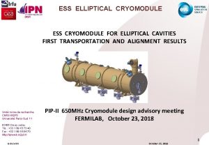
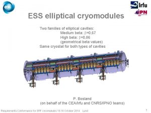
ESS ELLIPTICAL CRYOMODULE ESS CRYOMODULE FOR ELLIPTICAL CAVITIES


- Slides: 23

ESS ELLIPTICAL CRYOMODULE ESS CRYOMODULE FOR ELLIPTICAL CAVITIES Unité mixte de recherche CNRS-IN 2 P 3 Université Paris-Sud 11 91406 Orsay cedex Tél. : +33 1 69 15 73 40 Fax : +33 1 69 15 64 70 http: //ipnweb. in 2 p 3. fr G OLIVIER / JP THERMEAU SAFETY REVIEW LUND June 9 th, 2016 LUND June 9, 2016 1

ESS ELLIPTICAL CRYOMODULE G OLIVIER / JP THERMEAU LUND June 9, 2016 2

ESS ELLIPTICAL CRYOMODULE G OLIVIER / JP THERMEAU LUND June 9, 2016 3

CIRCUITS - CHARACTERISTICS Circuit Temperature (K) Pressure (bara) Volume (l) Control valve Safety device Thermal shield 40 - 50 19 - 19, 5 3 CV 60 (Kv 0. 8 m 3/h) SV 60 (24 barg) Helium inlet 4. 5 3 1 CV 03 (Kv 2. 8) SV 02 (3 barg) Couplers 4. 5 3 1. 3 Cooling down 4. 5 1. 5 CV 02 (Kv 0. 2) 2 - 4. 5 1 CV 01 (Kv 0. 04) Filling Low pressure Vacuum G OLIVIER / JP THERMEAU 2 0. 030 – 1. 43 219 (Diph. pipe half filled) CV 04 (Kv 71) 300 K RD 90 / RD 91 (0. 99 barg) CV 91 (1. 5 bara) SV 90 (0. 64 barg) SV 70 (0. 02 bar) LUND June 9, 2016 4

HELIUM DISTRIBUTION Jumper VLP circuit (8 l) Rupture disk & safety valves Rupture disk & purge valve + pressure gauges JT valve CV 01 Exchanger Cooling down valve (CV 02) Diphasic pipe (27 l) Helium tank (48 l) Coupler circuit (1, 3 l) Thermal shield circuit (3 l) G OLIVIER / JP THERMEAU Cooling down circuit (1. 5 l) LUND June 9, 2016 Filling line (1 l) 5

CAVITIES Ø neck 80 mm Øext tank 418 mm Medium beta High beta Internal volume: 48 l G OLIVIER / JP THERMEAU LUND June 9, 2016 6

CRYOGENIC INTERFACES Rupture disk & safety valves CV 01 Vacuum safety valve Jumper connections Rupture disk & purge valve & press. gauges CV 02 He coupler outlet (x 4) G OLIVIER / JP THERMEAU LUND June 9, 2016 7

VACUUM VESSEL : SAFETY DEVICE Minimum Set flow section pressure (mm²) (barg) 11200 Considered worst scenario: Rupture of 2 K phase separator Þ liquid helium fills the vacuum vessel Þ liquid helium mass : 30 kg Þ Volume of vessel : 6. 3 m 3 Þ helium mass flow : 4. 1 kg/s (1. 04 bara, 4. 76 K) G OLIVIER / JP THERMEAU 0. 02 Diameter of relief valve SV 70 : 200 mm LUND June 9, 2016 8

THERMAL SHIELD : Safety devices Minimum Set flow section pressure (mm²) (barg) 34 Considered worst scenario: loss of insulation vacuum Þ air fully condensates onto the CM thermal shield surface covered with 30 MLI Þ considered heat power density : 1. 5 k. W/m² Þ thermal shield (~24 m²): 36 k. W Þ helium mass flow : 0. 1 kg/s (25 bara, 66 K) G OLIVIER / JP THERMEAU LUND 24 Diameter of relief valve SV 60 : 10 mm June 9, 2016 9

COOLING DOWN AND COUPLER CIRCUITS A relief valve SV 90 associated with a control valve CV 90 (1. 5 bara) Minimum Set flow section pressure (mm²) (barg) 340 Considered worst scenario: Þ HP He supply: 3 bara, 5 K Þ Valves CV 01, CV 02, CV 03 fully opened (at kv max) Þ Valve CV 04 closed Þ helium mass flow : 0. 082 kg/s (1. 74 bara, 4. 85 K) G OLIVIER / JP THERMEAU 0. 64 Diameter of relief valve SV 90 : 25 mm Kv of CV 90 : 11 LUND June 9, 2016 10

LOW PRESSURE LINE G OLIVIER / JP THERMEAU LUND June 9, 2016 11

SAFETY STRATEGY FOR THE LOW PRESSURE CIRCUITS Operating constraints: Þ maximal allowable pressure of cavities is about 2 bar, Þ pressure required by the cryogenic plant is 1. 43 bar, Þ 1. 43 bar is close of the opening pressure of the safety valves, the pressure margin between the operating pressure and safety device is low. Safety strategy: Þ Two burst disks (RD 90 – RD 91) designed for accidental scenarios, Þ a safety valve (SV 90) designed for abnormal operation and to avoid the bursting of RD 90 or RD 91, Þ a control valve (CV 90) designed to limit the pressure at a level lower than the opening pressure of SV 90. G OLIVIER / JP THERMEAU LUND June 9, 2016 12

2 K VESSEL : SAFETY DEVICES FAILURE SCENARIOS (JP THERMEAU, Safety equipments for helium circuits) SCENARIOS Circuit Area (m²) Failure of the insulation vacuum Helium vessel 4 x 1. 53 Failure of the beam vacuum Cavity 4 x 1. 81 Failure of insulation and beam vacuum Vessel + cavity heat flux (k. W/m²) 6. 2 (10 MLI layers) 38 (air on cavity wall) Heat load (k. W) Mass flow (kg/s) 38 2 275 14. 5 312 16. 4 7. 25 Kg/s per bursting disk Most credible & critical Reference for the sizing of the safety devices Unlikely Minimum rupture disk diameter: 88 mm Maximum He volume to be evacuated: 200 l (about 30 Kg) G OLIVIER / JP THERMEAU LUND June 9, 2016 13

G OLIVIER / JP THERMEAU Ø 90 mm Ø 97 mm BURSTING DISK LUND June 9, 2016 Dimensions updated by Witzenmann on 2016/04/07 14

SUMMARY Name SV 60 SV 02 SV 90 CV 90 RD 90 - RD 91 SV 70 Minimum flow section (mm²) 34 Section of pipe 340 kv > 11 5300 11200 Practical diameter (mm) 10 10 25 25 100 200 Set pressure (barg) 24 3 0. 64 1. 5 bara 0. 99 0. 02 Pressure drop in the main line : Þ > 3%PS, Þ no risk to damage the cavities. The pressure margins between the burst disks and the safety valves are very low (100 to 200 mbar). G OLIVIER / JP THERMEAU LUND June 9, 2016 15

PRESSURE EQUIPMENT DIRECTIVE Breakdown of each circuit in elementary sections to check the product Ps x V and the compliance to the Pressure Equipment Directive. Each section is considered as a separate vessel. G OLIVIER / JP THERMEAU LUND June 9, 2016 16

PRESSURE EQUIPMENT DIRECTIVE 1. 04 48 Aim: remain in 3. 3 category G OLIVIER / JP THERMEAU Volume of the largest circuit vessel: the cavity helium tank LUND June 9, 2016 17

MECHANICAL BEHAVIOUR OF THE CAVITIES UNDER PRESSURE Max. pressure (test at 1, 25 Pmax): 2, 6 barg Maximum working gauge pressure: 2, 6/1, 25 = 2, 08 barg Pressure test scenario: - Cavity fully constrained - Pressure in the tank - Beam vacuum carried out The maximum pressure allowable is - 2. 60 bar for 50 MPa VM (worst scenario) - 3. 64 bar for 70 MPa VM (best scenario) (Andrea BIGNAMI, INFN LASA - PDR, LASA, 19 May 2016) Maximum Ps: 2, 08 -1, 013=1, 067 barg This value is very close to the limit of 1, 04 barg needed to stay in PED chapter 3. 3 G OLIVIER / JP THERMEAU LUND June 9, 2016 18

SAFETY DEVICES OPERATING RANGE ABSOLUTE PRESSURE Pmax = 2. 14 bar 2. 04 bar Bursting area of the rupture disk GAUGE PRESSURE Maximum pressure = 1. 1 PS = 1. 14 barg PS = MAWP = 1. 04 barg Rupture disk outlet to the atmosphere at 1 bara Bursting pressure = 0. 99 barg ± 0. 05 bar 1. 94 bar 0. 94 barg Pressure margin ~ 0. 2 bar 1. 74 bar Set pressure = 0. 64 barg ± 5% of the 0. 95 Pset ~ 0. 61 barg relief valve 1. 55 bar 1. 5 bar Min. pressure to allow the closing of the relief valve: 0. 9 x 0. 61 ~ 0. 55 barg PLC Control valve ~ 0. 5 barg 1. 43 bar Min. /Max. operating pressure of the cryogenic plant: ~ 0. 43 barg (cooling down phase) 30 mbar Pressure operation at 2 K Operating G OLIVIER / JP THERMEAU Safety valve outlet to SV relief line at 1 bara 1. 05 Pset ~ 0. 67 barg Opening area pressure area Max. pressure when the relief valve is open: 1. 1 x 0. 67 ~ 0. 74 barg LUND June 9, 2016 19

SAFETY DEVICES OPERATING RANGE ABSOLUTE PRESSURE Pmax = 2. 14 bar 2. 04 bar Bursting area of the rupture disk 1. 94 bar 1. 84 bar PS = MAWP = 1. 04 barg Rupture disk outlet to the atmosphere at 1 bara 0. 94 barg Max. pressure when the relief valve is open: 1. 1 x 0. 67 ~ 0. 74 barg (% outlet circuit) 1. 05 Pset ~ 0. 67 barg (% outlet circuit) Opening area Set pressure = 0. 64 barg ± 5% (% outlet circuit) of the 0. 95 Pset ~ 0. 61 barg (% outlet circuit) relief valve 1. 65 bar 1. 5 bar Safety valve outlet to SV relief line at 1. 1 bara Min. pressure to allow the closing of the relief valve: 0. 9 x 0. 61 ~ 0. 55 barg (% outlet circuit) PLC Control valve ~ 0. 5 barg 1. 43 bar Min. /Max. operating pressure of the cryogenic plant: ~ 0. 43 barg 30 mbar Pressure operation at 2 K Operating G OLIVIER / JP THERMEAU Maximum pressure = 1. 1 PS = 1. 14 barg Bursting pressure = 0. 99 barg ± 0. 05 bar Pressure margin ~ 0. 1 bar pressure area GAUGE PRESSURE LUND June 9, 2016 20

SAFETY DEVICES OPERATING RANGE ABSOLUTE PRESSURE Pmax > 2. 14 bar >2. 04 bar Bursting area of the rupture disk GAUGE PRESSURE Increase of the Ps value, if exhaust line > Patm Maximum pressure = 1. 1 PS PS = MAWP > 1. 04 barg (% outlet circuit) Bursting pressure = 0. 99 barg ± 0. 05 bar (% outlet circuit) >1. 94 bar 0. 94 barg (% outlet circuit) Rupture disk outlet to exhaust line > 1 bara Pressure margin > 0. 1 bar 1. 84 bar 1. 05 Pset ~ 0. 67 barg (% outlet circuit) Opening area Set pressure = 0. 64 barg ± 5% (% outlet circuit) of the 0. 95 Pset ~ 0. 61 barg (% outlet circuit) relief valve 1. 65 bar 1. 5 bar G OLIVIER / JP THERMEAU Safety valve outlet to SV relief line at 1. 1 bara Min. pressure to allow the closing of the relief valve: 0. 9 x 0. 61 ~ 0. 55 barg (% outlet circuit) PLC Control valve ~ 0. 5 barg 1. 43 bar Min. /Max. operating pressure of the cryogenic plant: ~ 0. 43 barg 30 mbar Pressure operation at 2 K Operating pressure area Max. pressure when the relief valve is open: 1. 1 x 0. 67 ~ 0. 74 barg (% outlet circuit) LUND June 9, 2016 21

REMAINING ISSUES - Value of Ps to remain in PED 3. 3 category - Value of Ps to avoid any yielding of the cavities - Impact of the helium discharge of one cryomodule on the other disks: increase of the bursting pressure Exhaust line at atmospheric pressure? (lost of the helium? ) G OLIVIER / JP THERMEAU LUND June 9, 2016 22

ESS ELLIPTICAL CRYOMODULE THANK YOU FOR YOUR ATTENTION G OLIVIER / JP THERMEAU LUND June 9, 2016 23
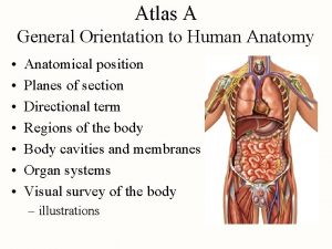
 Body orientation definition
 Arytenoid muscle
 The anterior and posterior body cavities
 Body cavities
 Classification of body membranes
 Quadrants of the body
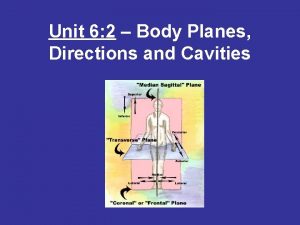
 Body planes directions and cavities worksheet
 Major body cavities
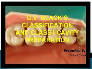
 G.v. black classification of caries
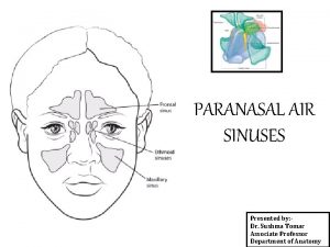
 Air containing cavities in the bones around the nose
 Does sucralose cause cavities
 The brain contains four lined cavities called
 3 planes of the body
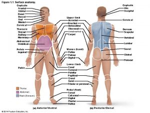
 Body cavities labeled
 Plantago tincture for cavities
 Animal body cavities
 Body cavity of echinoderms
 Hypochondriac region
 Body cavities
 Hands facing forward
 Thoracic membranes
 Abdominal cavity
 Chapter 7.2 body planes, directions, and cavities
 Left lower quadrant organs
