Cavities Cryomodules CW requirements Vincent Roger P 2


- Slides: 17

Cavities & Cryomodules - CW requirements Vincent Roger P 2 MAC 26 -28 March 2018 In partnership with: India/DAE Italy/INFN UK/STFC France/CEA/Irfu, CNRS/IN 2 P 3

Outline 1. Introduction 2. Design strategy for CW operation • • Cavities Cryomodule 3. Pulsed operation 4. Summary 2 26 -28 March 2018 Vincent Roger | Cavities & Cryomodules - CW requirements

1. Introduction • PIP-II FRS: SSR 1 SSR 2 LB 650 HB 650 Cryomodule requirements Cryomodule ED 0001316 ED 0001829 ED 0001830 ED 0001322 Cavity ED 0001317 ED 0001854 ED 0001834 ED 0001321 Cavity requirements Coupler requirements 3 26 -28 March 2018 Vincent Roger | Cavities & Cryomodules - CW requirements Coupler ED 0001777 ED 0003645

1. Introduction Vacuum vessel Dressed cavity 2 -Phase He pipe Thermal shield 35 -50 K 5 K Line Support post Coupler • Critical elements for CW operation – Coupler design – Thermal intercept design – Heat loads – Sensitivity to LHe pressure fluctuations 4 26 -28 March 2018 Vincent Roger | Cavities & Cryomodules - CW requirements Strong-back

2. Design strategy / Cavity Cavities have been designed and optimized to operate at high Q 0 by minimizing df/dp. This design strategy is essential to reduce as much as possible the cost of the project. Accelerator gradient The best is to have a passive compensation by having a parallel approach in performing RF and mechanical analyses. PIP II requirements: < 25 Hz/mbar f 0 5 26 -28 March 2018 Frequency Vincent Roger | Cavities & Cryomodules - CW requirements

2. Design strategy / Cavity • SSR 1 Cavities The jacketed SSR 1 cavities were designed to have very low sensitivity to helium pressure fluctuations. We physically coupled the Nb cavity and the helium vessel such that we obtain a combination of cavity walls deformations (x 1+x 2) and (x 3+x 4) giving a ���� /���� close to 0. By courtesy of D. Passarelli df/dp (Hz/mbar) Bare cavity (with transition ring) With He vessel (without tuner) Fully integrated (estimation) S 106 S 107 S 108 S 109 S 110 S 111 S 112 S 113 S 114 -561 -553. 5 -555. 1 -568. 8 -525. 8 -524. 6 -544. 7 -557. 2 8 8 -1. 2 5. 4 7. 9 2. 7 9 6. 3 10 4 4 0 2 4 2 5 3 5 The measured df/dp is very small < 10 Hz/mbar • SSR 2 Cavities BARC is in charge of the design of SSR 2 cavities. They are following the same design strategy to optimize the design. 6 26 -28 March 2018 Vincent Roger | Cavities & Cryomodules - CW requirements

2. Design strategy / Cavity By courtesy of I. Gonin • HB 650 Cavities 0. 9 Thickness 4 mm 50 40 df/dp The df/dp is below the requirement. Around 10 -15 Hz/mbar for a tuner stiffness of 40 k. N/mm. 60 FRS 30 0. 92 Thickness 4 mm 20 10 0. 92 Thickness 3. 75 mm 0 0 20 40 60 80 100 Tuner stiffness (k. N/mm) • LB 650 Cavities VECC is in charge of the RF and mechanical design of LB 650 cavities. The design is not yet finalized, but preliminary calculations shows that the df/dp will be close to the requirements. 7 26 -28 March 2018 0. 9 Thickness 3. 75 mm Vincent Roger | Cavities & Cryomodules - CW requirements

2. Design strategy / Cryomodule SSR 1, SSR 2, LB 650 & HB 650 cryomodules share the same design strategy. SSR 1 Cryomodule HB 650 Cryomodule 8 26 -28 March 2018 Vincent Roger | Cavities & Cryomodules - CW requirements

2. Design strategy / Cryomodule SSR 1, SSR 2, LB 650 & HB 650 cryomodules share the same design strategy. Pipe B - Pumping line MAWP: 2. 05 bar warm, 4. 1 bar cold Pipe G - 2 phase He & chimney MAWP: 2. 05 bar warm, 4. 1 bar cold Pipe I - Helium guard of the current leads MAWP: 4. 1 bar Pipe C & D - 5 K line MAWP: 20 bar Pipe A - 2 K supply MAWP: 20 bar Pipe E & F - 35 -50 K line MAWP: 20 bar Pipe H - Cool down / warm up line MAWP: 20 bar SSR 1 Cryomodule 9 26 -28 March 2018 Vincent Roger | Cavities & Cryomodules - CW requirements

2. Design strategy / Cryomodules heat loads meet the requirements. 10 26 -28 March 2018 Vincent Roger | Cavities & Cryomodules - CW requirements

2. Design strategy / Cryomodule The P&ID is also similar for all cryomodules. For the cryomodule point of view, the requirement is to warrant a pressure change bellow 0. 1 mbar during operation. 11 26 -28 March 2018 Vincent Roger | Cavities & Cryomodules - CW requirements

2. Design strategy / Cryomodule To avoid thermal acoustic oscillations, a thermal straps has been placed on the line going to the pressure transducers. Without thermal intercept 12 26 -28 March 2018 With thermal intercept Vincent Roger | Cavities & Cryomodules - CW requirements

2. Design strategy / Cryomodule Calculations have been done in order to demonstrate that all the pipes of SSR 1 cryomodule have been designed per venting requirements. Loss of insulating vacuum Cavity vacuum loss Magnet quench Considered diameter Needed diameter for the chimney of the solenoid Needed diameter for the chimney of the dressed cavity Needed diameter for the 2 -phase helium pipe Needed diameter for the relief line 6. 9 mm 31. 5 mm 92. 0 mm 92. 5 mm 2. 3 mm 32. 3 mm 91. 6 mm 26. 8 mm - 53. 5 mm 35 mm 57 mm 146. 8 mm 108. 2 mm Pressure drop analysis have ben performed to estimate the available relief capacity compared to the required mass flow rate. The two-phase helium pipe has been oversized in order to increase the gas volume and therefore the pressure stability. 13 26 -28 March 2018 Vincent Roger | Cavities & Cryomodules - CW requirements

2. Design strategy / Cryomodule To mitigate thermal acoustic oscillations, helium bath instability, and structural vibrations, the experience from LCLS II is an asset. Helium inlet at 2 K Interface with the JT valve Thermal intercept Outlet By courtesy of S. Cheban 14 26 -28 March 2018 Vincent Roger | Cavities & Cryomodules - CW requirements Inlet

2. Design strategy / Cryomodule Thermal straps have been designed connecting the cryogenic lines to the coupler thermal intercepts. Requirements from ED 0001777: Temperature at 5 K intercept Temperature at 35 -50 K intercept Maximum 5 K heat load SSR 1 Maximum 35 -50 K heat load SSR 1 15 26 -28 March 2018 Vincent Roger | Cavities & Cryomodules - CW requirements < 15 K < 125 K < 3. 4 W < 11. 0 W

3. Pulsed operation In pulsed operation, the main driving parameter for cavity design is the Lorentz Force Detuning coefficient. All PIP-II cavities meet the requirements, and this case we rely on the active tuning : For cryomodules, the pulsed operation is less critical than the CW operation since the dynamic heat loads are lower. 16 26 -28 March 2018 Vincent Roger | Cavities & Cryomodules - CW requirements

Summary • All components support CW and pulsed operation – For cavities, the design strategy is first to mitigate the df/dp and then to optimize the design in order to decrease the Lorentz Force Detuning coefficient due to the fact active compensation can be used with the tuner. – For cryomodules, CW or pulsed operation doesn’t change deeply the design. Pressure stability, thermal acoustic oscillations and heat loads, thermal straps design are still the driving parameters. 17 26 -28 March 2018 Vincent Roger | Cavities & Cryomodules - CW requirements
 The brain contains four lined cavities called
 Body cavities labeled
 Jhuma biswas homeopathy
 Supine palm
 Excretory organs in echinoderms
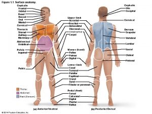
 Abdominopelvic regions
 What is sweeteners
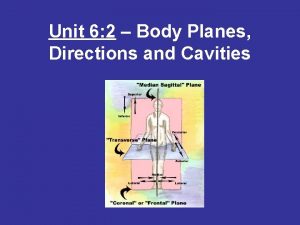
 Unit 6.2 body planes directions and cavities
 Anatomical position hands
 Orbital on body
 Animal body cavities
 Chapter 7.2 body planes, directions, and cavities
 Body planes directions and cavities
 Health science 20
 Cricothyroid muscle.
 The anterior and posterior body cavities
 Body cavities
 Nine regions of the abdominopelvic cavity
