Electroplating Recommendations for a new and independent setup

- Slides: 28
Electroplating Recommendations for a new and independent setup
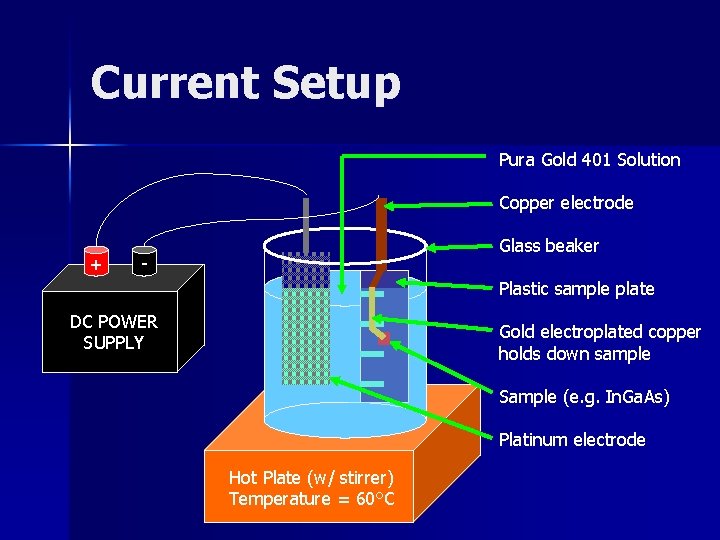
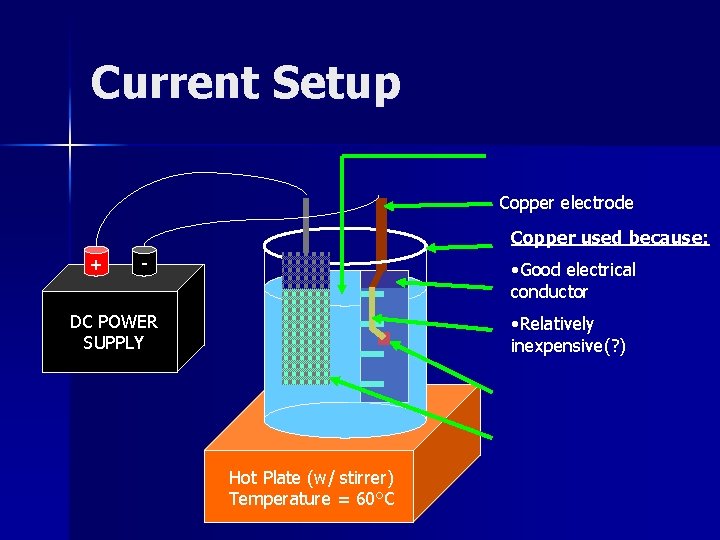
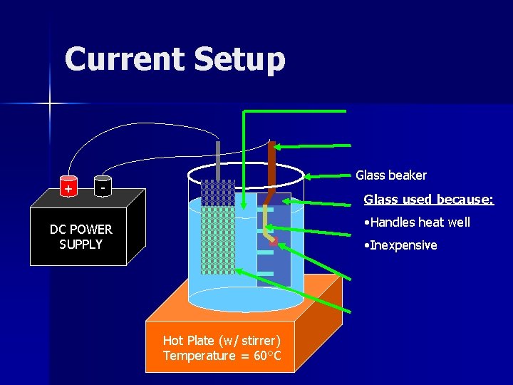
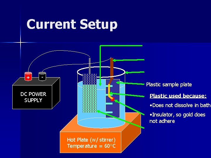
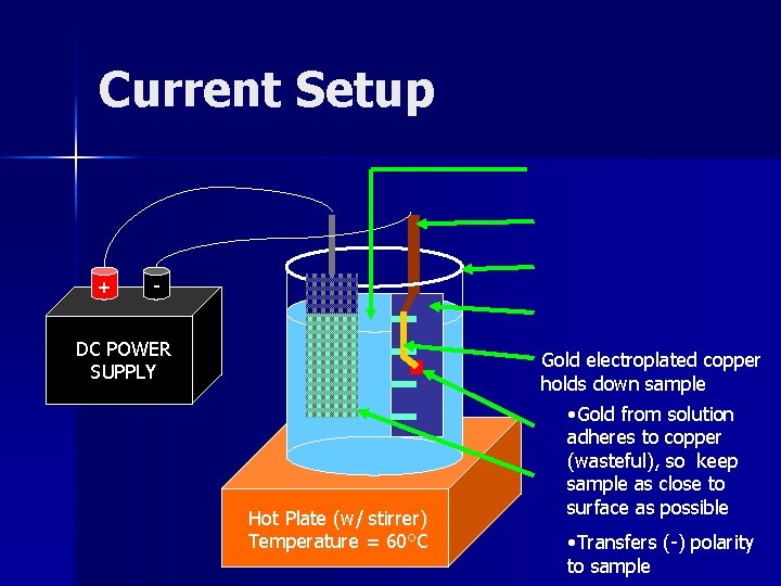
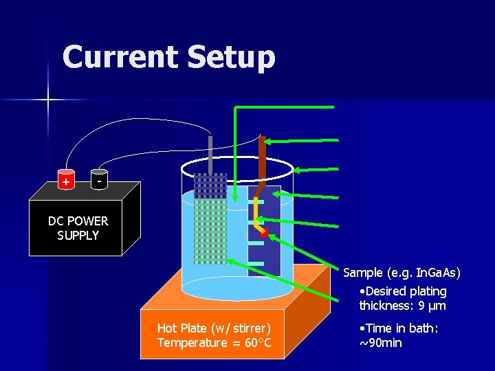
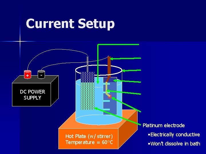
Current Setup Pura Gold 401 Solution Copper electrode + Glass beaker - Plastic sample plate DC POWER SUPPLY Gold electroplated copper holds down sample Sample (e. g. In. Ga. As) Platinum electrode Hot Plate (w/ stirrer) Temperature = 60°C
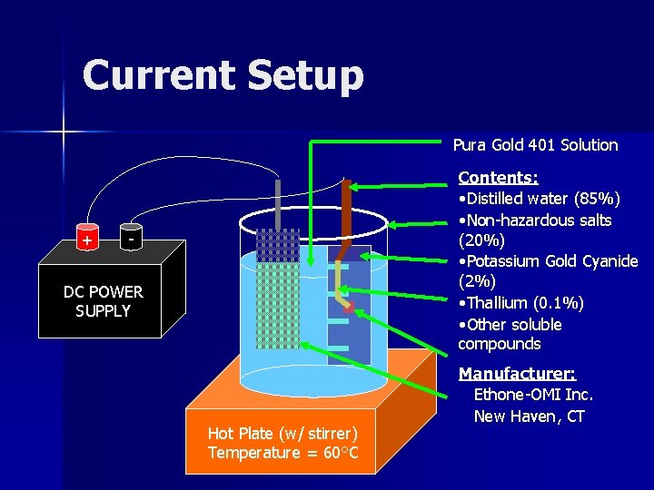
Current Setup Pura Gold 401 Solution + Contents: • Distilled water (85%) • Non-hazardous salts (20%) • Potassium Gold Cyanide (2%) • Thallium (0. 1%) • Other soluble compounds - DC POWER SUPPLY Hot Plate (w/ stirrer) Temperature = 60°C Manufacturer: Ethone-OMI Inc. New Haven, CT
Current Setup Copper electrode Copper used because: + - • Good electrical conductor DC POWER SUPPLY • Relatively inexpensive(? ) Hot Plate (w/ stirrer) Temperature = 60°C
Current Setup + Glass beaker - Glass used because: • Handles heat well DC POWER SUPPLY • Inexpensive Hot Plate (w/ stirrer) Temperature = 60°C
Current Setup + Plastic sample plate DC POWER SUPPLY Plastic used because: • Does not dissolve in bath • Insulator, so gold does not adhere Hot Plate (w/ stirrer) Temperature = 60°C
Current Setup + - DC POWER SUPPLY Gold electroplated copper holds down sample Hot Plate (w/ stirrer) Temperature = 60°C • Gold from solution adheres to copper (wasteful), so keep sample as close to surface as possible • Transfers (-) polarity to sample
Current Setup + - DC POWER SUPPLY Sample (e. g. In. Ga. As) • Desired plating thickness: 9 µm Hot Plate (w/ stirrer) Temperature = 60°C • Time in bath: ~90 min
Current Setup + - DC POWER SUPPLY Platinum electrode Hot Plate (w/ stirrer) Temperature = 60°C • Electrically conductive • Won’t dissolve in bath
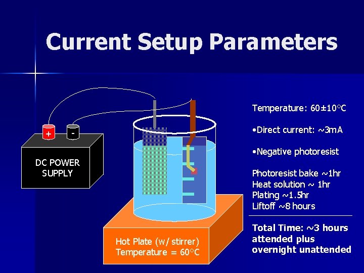
Current Setup Parameters Temperature: 60± 10°C + • Direct current: ~3 m. A - • Negative photoresist DC POWER SUPPLY Photoresist bake ~1 hr Heat solution ~ 1 hr Plating ~1. 5 hr Liftoff ~8 hours Hot Plate (w/ stirrer) Temperature = 60°C Total Time: ~3 hours attended plus overnight unattended
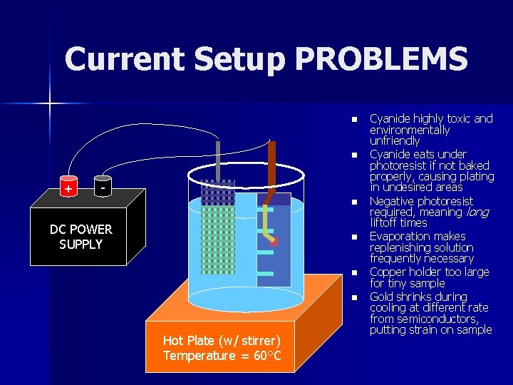
Current Setup PROBLEMS n n + n DC POWER SUPPLY n n n Hot Plate (w/ stirrer) Temperature = 60°C Cyanide highly toxic and environmentally unfriendly Cyanide eats under photoresist if not baked properly, causing plating in undesired areas Negative photoresist required, meaning long liftoff times Evaporation makes replenishing solution frequently necessary Copper holder too large for tiny sample Gold shrinks during cooling at different rate from semiconductors, putting strain on sample
Possible New Strategies o Replace Platinum anode with Titanium or Cadmium coated with Platinum (if this is not currently the case), reducing cost o Alternative plating materials o Cyanide vs. non-cyanide baths o Electroless plating o Back-side plating o Computerized process
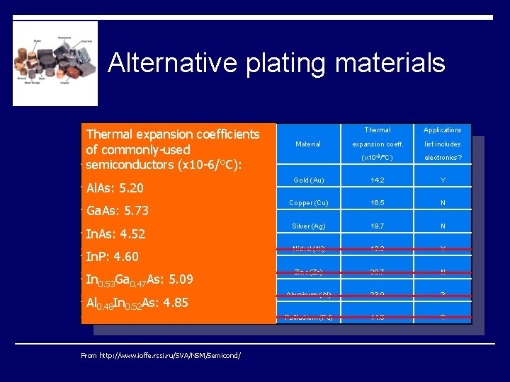
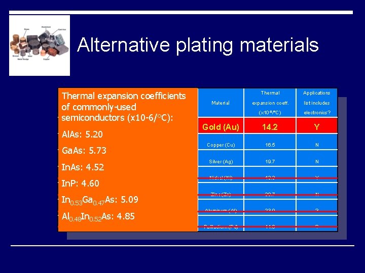
Alternative plating materials o Important factors: n Thermal Conductivity p Plating designed for cooling n Adhesion p Must adhere well to III-V compounds in samples and copper in heat sink n Density p Denser plating means better properties n Thermal Expansion Coefficient p When cooling occurs, a TEC different from that of the plated material causes stress on the system
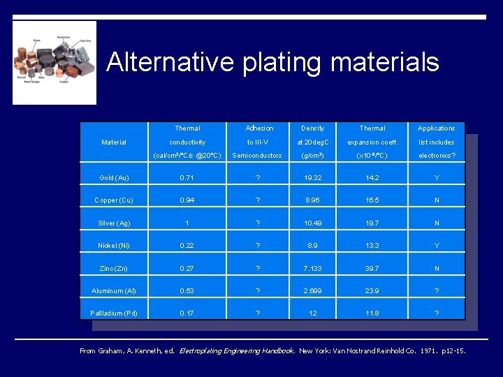
Alternative plating materials Thermal Adhesion Density Thermal Applications Material conductivity to III-V at 20 deg. C expansion coeff. list includes (cal/cm 3/°C/s @20°C) Semiconductors (g/cm 3) (x 10 -6/°C) electronics? Gold (Au) 0. 71 ? 19. 32 14. 2 Y Copper (Cu) 0. 94 ? 8. 96 16. 5 N Silver (Ag) 1 ? 10. 49 19. 7 N Nickel (Ni) 0. 22 ? 8. 9 13. 3 Y Zinc (Zn) 0. 27 ? 7. 133 39. 7 N Aluminum (Al) 0. 53 ? 2. 699 23. 9 ? Pallladium (Pd) 0. 17 ? 12 11. 8 ? From Graham, A. Kenneth, ed. Electroplating Engineering Handbook. New York: Van Nostrand Reinhold Co. 1971. p 12 -15.
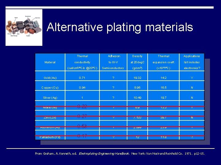
Alternative plating materials Thermal Adhesion Density Thermal Applications Material conductivity to III-V at 20 deg. C expansion coeff. list includes (cal/cm 3/°C/s @20°C) Semiconductors (g/cm 3) (x 10 -6/°C) electronics? Gold (Au) 0. 71 ? 19. 32 14. 2 Y Copper (Cu) 0. 94 ? 8. 96 16. 5 N Silver (Ag) 1 ? 10. 49 19. 7 N Nickel (Ni) 0. 22 ? 8. 9 13. 3 Y Zinc (Zn) 0. 27 ? 7. 133 39. 7 N Aluminum (Al) 0. 53 ? 2. 699 23. 9 ? Pallladium (Pd) 0. 17 ? 12 11. 8 ? From Graham, A. Kenneth, ed. Electroplating Engineering Handbook. New York: Van Nostrand Reinhold Co. 1971. p 12 -15.
Alternative plating materials Thermal expansion coefficients of commonly-used semiconductors (x 10 -6/°C): Thermal Applications expansion coeff. list includes (x 10 -6/°C) electronics? Gold (Au) 14. 2 Y Ga. As: 5. 73 Copper (Cu) 16. 5 N In. As: 4. 52 Silver (Ag) 19. 7 N In. P: 4. 60 Nickel (Ni) 13. 3 Y Zinc (Zn) 39. 7 N Aluminum (Al) 23. 9 ? Pallladium (Pd) 11. 8 ? Al. As: 5. 20 In 0. 53 Ga 0. 47 As: 5. 09 Al 0. 48 In 0. 52 As: 4. 85 From http: //www. ioffe. rssi. ru/SVA/NSM/Semicond/ Material
Alternative plating materials Thermal expansion coefficients of commonly-used semiconductors (x 10 -6/°C): Thermal Applications expansion coeff. list includes (x 10 -6/°C) electronics? Gold (Au) 14. 2 Y Ga. As: 5. 73 Copper (Cu) 16. 5 N In. As: 4. 52 Silver (Ag) 19. 7 N In. P: 4. 60 Nickel (Ni) 13. 3 Y Zinc (Zn) 39. 7 N Aluminum (Al) 23. 9 ? Pallladium (Pd) 11. 8 ? Al. As: 5. 20 In 0. 53 Ga 0. 47 As: 5. 09 Al 0. 48 In 0. 52 As: 4. 85 Material
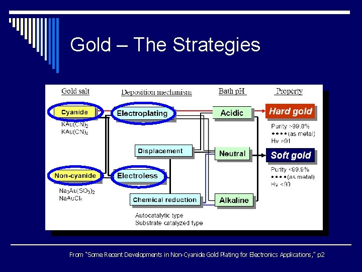
Gold – The Strategies From “Some Recent Developments in Non-Cyanide Gold Plating for Electronics Applications, ” p 2
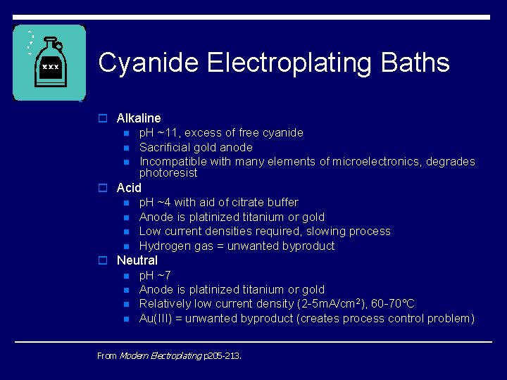
Cyanide Electroplating Baths o Alkaline n n n p. H ~11, excess of free cyanide Sacrificial gold anode Incompatible with many elements of microelectronics, degrades photoresist o Acid n n p. H ~4 with aid of citrate buffer Anode is platinized titanium or gold Low current densities required, slowing process Hydrogen gas = unwanted byproduct o Neutral n n p. H ~7 Anode is platinized titanium or gold Relatively low current density (2 -5 m. A/cm 2), 60 -70°C Au(III) = unwanted byproduct (creates process control problem) From Modern Electroplating p 205 -213.
Cyanide vs. Non-Cyanide o Gold Cyanide complex = more stable o More widely used and available o Health/safety concerns o Lower plating efficiency o Incompatible with positive photoresists o Residual stress can be controlled in non- cyanide baths n But this uses Thallium, a health hazard From Modern Electroplating p 213 -14.
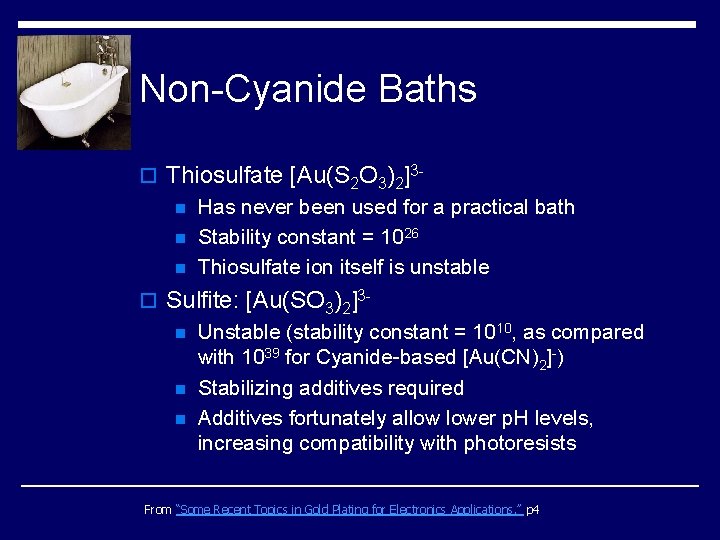
Non-Cyanide Baths o Thiosulfate [Au(S 2 O 3)2]3 n Has never been used for a practical bath n Stability constant = 1026 n Thiosulfate ion itself is unstable o Sulfite: [Au(SO 3)2]3 n Unstable (stability constant = 1010, as compared with 1039 for Cyanide-based [Au(CN)2]-) n Stabilizing additives required n Additives fortunately allow lower p. H levels, increasing compatibility with photoresists From “Some Recent Topics in Gold Plating for Electronics Applications, ” p 4
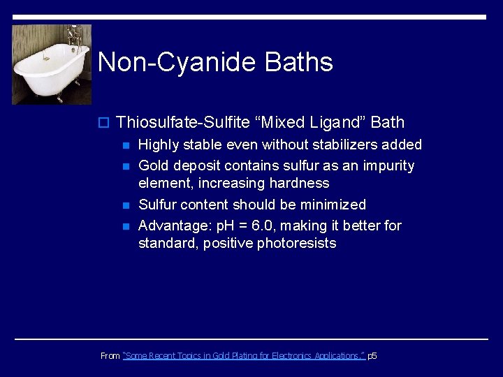
Non-Cyanide Baths o Thiosulfate-Sulfite “Mixed Ligand” Bath n Highly stable even without stabilizers added n Gold deposit contains sulfur as an impurity element, increasing hardness n Sulfur content should be minimized n Advantage: p. H = 6. 0, making it better for standard, positive photoresists From “Some Recent Topics in Gold Plating for Electronics Applications, ” p 5
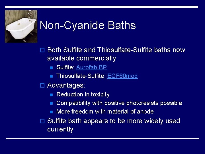
Non-Cyanide Baths o Both Sulfite and Thiosulfate-Sulfite baths now available commercially n n Sulfite: Aurofab BP Thiosulfate-Sulfite: ECF 60 mod o Advantages: n Reduction in toxicity n Compatibility with positive photoresists possible n More freedom with material of anode o Sulfite bath appears to be more widely used currently
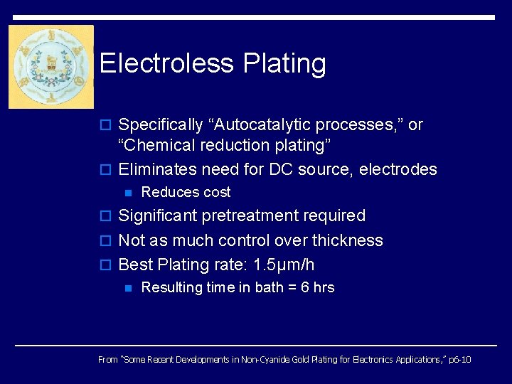
Electroless Plating o Specifically “Autocatalytic processes, ” or “Chemical reduction plating” o Eliminates need for DC source, electrodes n Reduces cost o Significant pretreatment required o Not as much control over thickness o Best Plating rate: 1. 5µm/h n Resulting time in bath = 6 hrs From “Some Recent Developments in Non-Cyanide Gold Plating for Electronics Applications, ” p 6 -10
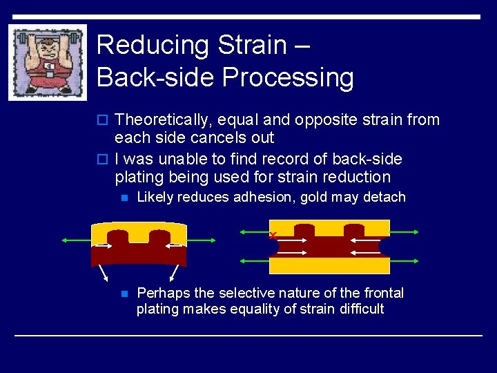
Reducing Strain – Back-side Processing o Theoretically, equal and opposite strain from each side cancels out o I was unable to find record of back-side plating being used for strain reduction n Likely reduces adhesion, gold may detach x n Perhaps the selective nature of the frontal plating makes equality of strain difficult
Computerized process o Robotic arm performed functions as early as 1982 o Advantages: n n Assured uniformity in plating thickness Researcher need not be present(? ) o Disadvantages: n Cost increase n Space issues o Available primarily for large-scale, non- research operations
Recommendations from Igor o Reference Electrode o Plastic lid (e. g. polystyrene) should be used to prevent evaporation o Better, smaller sample holder o Greater thickness control (how? ) n Deposit gold in troughs just below ridges p Better heat conduction
Sources Journals: o Green, T. A. , Liew, M. J. , and Roy S. , ”Electrodeposition of Gold from a Thiosulfate-Sulfite Bath for Microelectronic Applications” Journal of The Electrochemical Society. v 150 n 3 C 104 -C 110. 2003. o Holliday, R. and Goodman, P. “Going for Gold. ” IEEE Review. May 2002. p 15 -19. o Kato, Masaru and Okinaka, Yutaka. “Some Recent Developments in Gold Plating for Electronics Applications. ” ? ? ? p 1 -15. o Okinaka, Y. and Hoshino, M. “Some Recent Topics in Gold Plating for Electronics Applications. ” Electrochemical Technology Applications in Electronics. Proceedings of the Third International Symposium (Electrochemical Society Proceedings Vol. 99 -34), 2000, p 132 -44. o Wang, K. , Beica, R. , and Brown, N. “Soft gold electroplating from a non-cyanide bath for electronic applications. ” IEEE/CPMT/SEMI 29 th International Electronics Manufacturing Technology Symposium. 2004. p 242 -6. o Young, E. , et. al. “Characterization of Electroplated Gold for Back-Side Processing of Ga. As Wafers. ” 2002 Ga. As MANTECH Conf. Digest of Papers. 2002. p 180 -3. o Osaka, T. , Okinaka, Y. , and Kato, M. “Non-cyanide electrolytes for electroytic and electroless gold deposition processes. ” ? ? ? . Books: o Graham, A. Kenneth, ed. Electroplating Engineering Handbook. New York: Van Nostrand Reinhold Co. 1971. o Kanani, Nasser. Electroplating: Basic Principles, Processes, and Practice. Oxford: Elsevier Ltd. 2004. o Schlesinger, M. and Paunovic, M. Modern Electroplating: Fourth Edition. New York: John Wiley & Sons, Inc. 2000. Note: the Okinaka sources each present some unique information, but they do have a great deal of overlap.