Effectors and Actuators Key points Mechanisms for acting

- Slides: 38
Effectors and Actuators Key points: • Mechanisms for acting on the world • ‘Degrees of freedom’ • Methods of locomotion: wheels, legs and beyond • Methods of manipulation: arms and grippers • Methods of actuation and transmission • The problem: mapping between input signals to actuators and the desired effect in the world
Effector: a device that affects the physical environment • Wheels on a mobile robot – Or legs, wings, fins… – Whole body might push objects • Grippers on an assembly robot – Or welding gun, paint sprayer • Speaker, light, tracing-pen
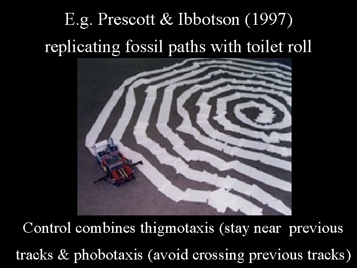
E. g. Prescott & Ibbotson (1997) replicating fossil paths with toilet roll Control combines thigmotaxis (stay near previous tracks & phobotaxis (avoid crossing previous tracks)
Effector: a device that affects the physical environment • Choice of effectors sets upper limit on what the robot can do • Usually categorised as locomotion (vehicle moving itself) or manipulation (an arm moving things) • In both cases can consider the degrees of freedom in the design
Degrees of freedom • General meaning: How many parameters needed to specify something? E. g. for an object in space have: X, Y, Z position Roll, pitch, yaw rotation Total of 6 degrees of freedom How many d. o. f. to specify a vehicle on a flat plane?
Degrees of freedom In relation to robots could consider: • How many joints/articulations/moving parts? • How many individually controlled moving parts? • How many independent movements with respect to a co-ordinate frame? • How many parameters to describe the position of the whole robot or its end effector?
• How many moving parts? • If parts are linked need fewer parameters to specify them. • How many individually controlled moving parts? • Need that many parameters to specify robot’s configuration. • Often described as ‘controllable degrees of freedom’ • But note may be redundant e. g. two movements may be in the same axis • Alternatively called ‘degrees of mobility’
• How many degrees of mobility in the human arm? • Redundant manipulator Degrees of mobility > degrees of freedom • Result is that have more than one way to get the end effector to a specific position
• How many independent movements with respect to a co-ordinate frame? • Controlled degrees of freedom of the robot • May be less than degrees of mobility • How many parameters to describe the position of the whole robot or its end effector? • For fixed robot, d. o. f. of end effector is determined by d. o. f. of robot (max 6) • Mobile robot on plane can reach position described by 3 d. o. f. , but if robot has fewer d. o. f. then it cannot do it directly – it is non-holonomic
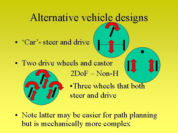
Alternative vehicle designs • ‘Car’- steer and drive • Two drive wheels and castor 2 Do. F – Non-H • Three wheels that both steer and drive • Note latter may be easier for path planning but is mechanically more complex
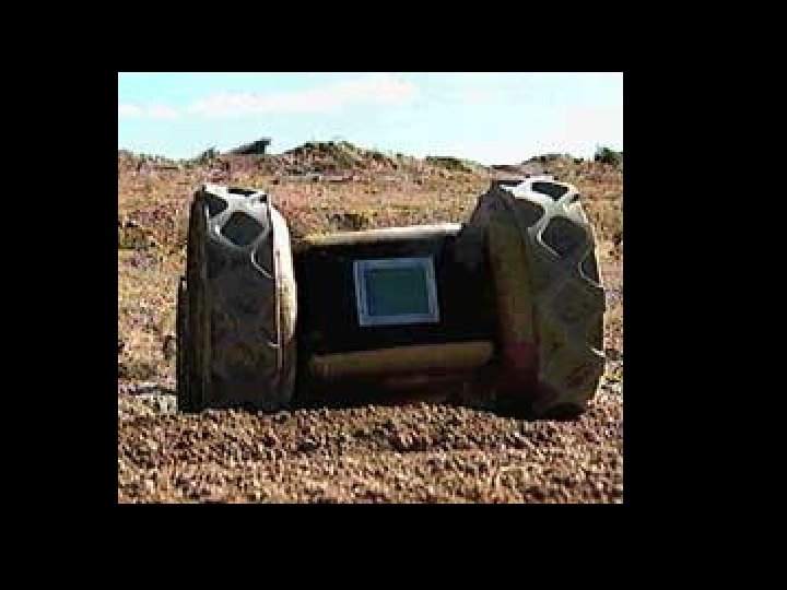
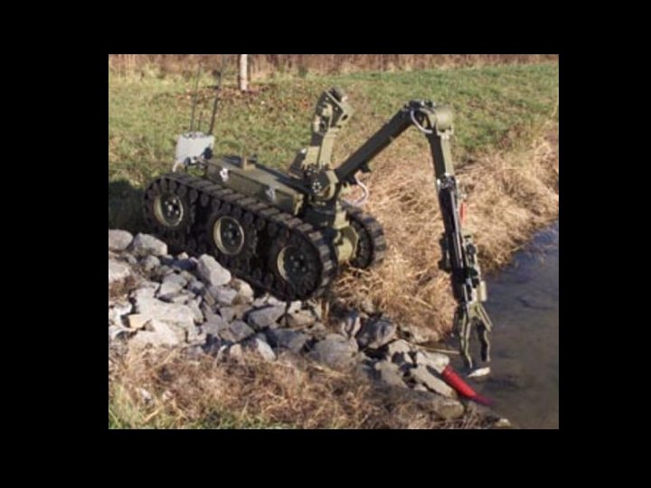
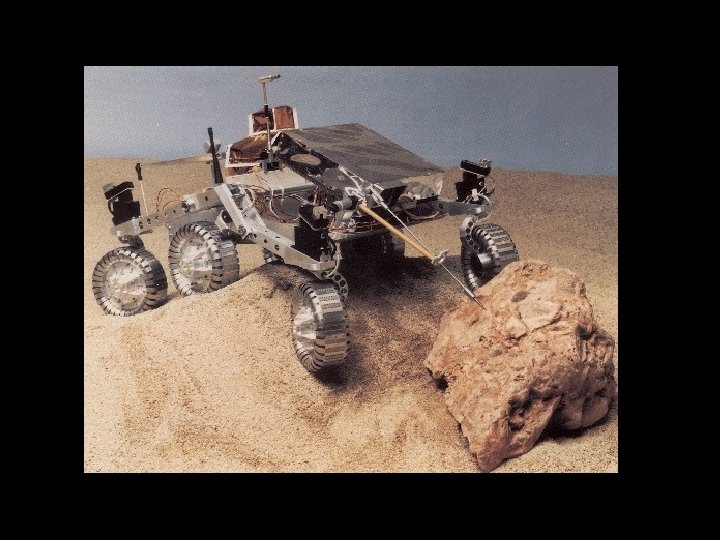
Locomotion on uneven terrain • • Use the world (ramps etc. ) Larger wheels Suspension Tracks
Locomotion on uneven terrain • • Use the world (ramps etc. ) Larger wheels Suspension Tracks • Alternative is to use legs – (but note wheels and variants are faster, for less energy, and usually simpler to control)
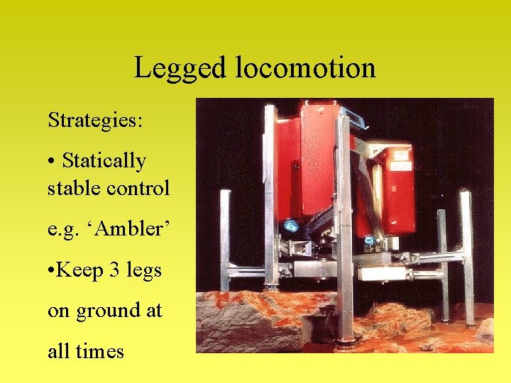
Legged locomotion Strategies: • Statically stable control e. g. ‘Ambler’ • Keep 3 legs on ground at all times
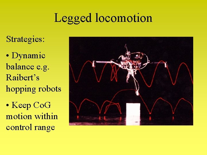
Legged locomotion Strategies: • Dynamic balance e. g. Raibert’s hopping robots • Keep Co. G motion within control range
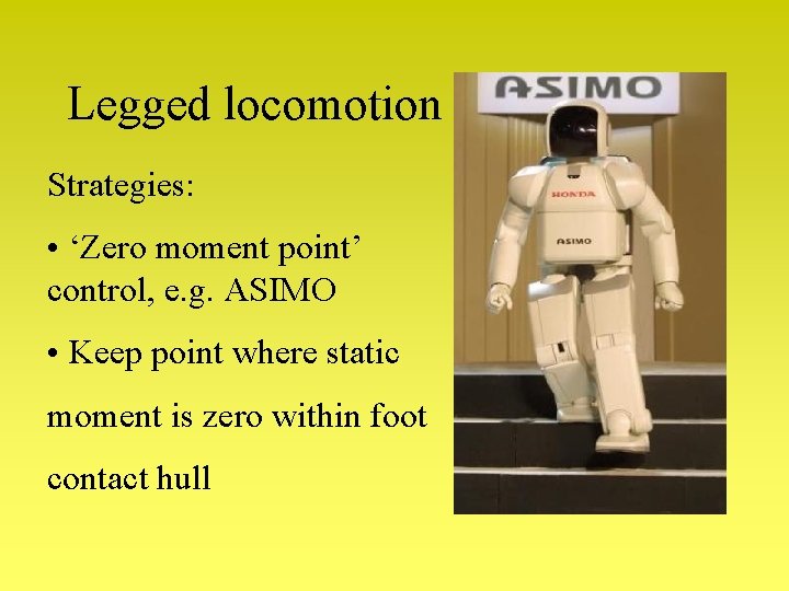
Legged locomotion Strategies: • ‘Zero moment point’ control, e. g. ASIMO • Keep point where static moment is zero within foot contact hull
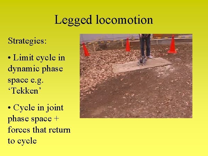
Legged locomotion Strategies: • Limit cycle in dynamic phase space e. g. ‘Tekken’ • Cycle in joint phase space + forces that return to cycle
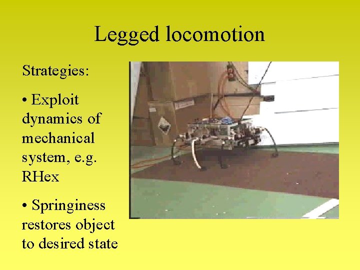
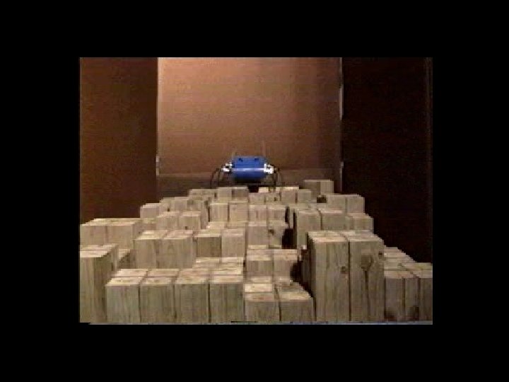
Legged locomotion Strategies: • Exploit dynamics of mechanical system, e. g. RHex • Springiness restores object to desired state
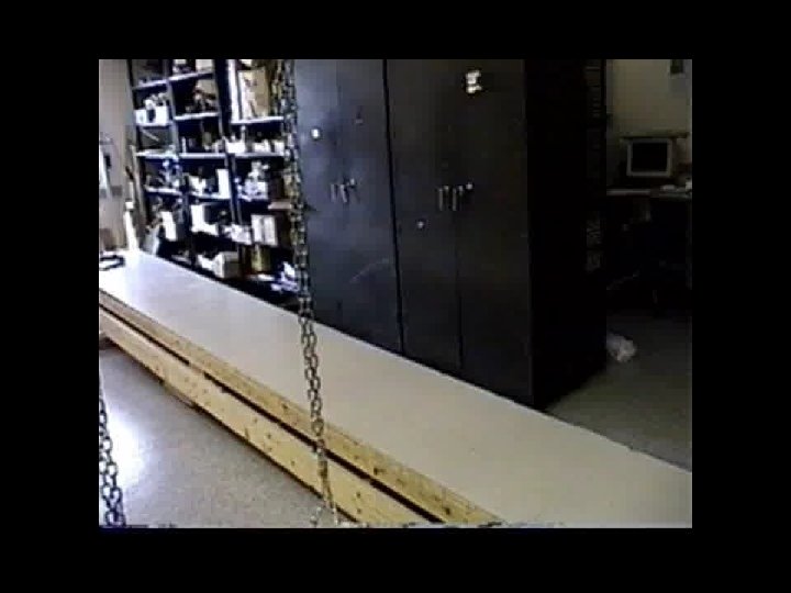
Legged locomotion Strategies: • Exploit natural dynamics with only gravity as the actuator • E. g. passive walkers
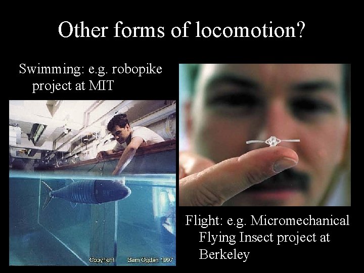
Other forms of locomotion? Swimming: e. g. robopike project at MIT Flight: e. g. Micromechanical Flying Insect project at Berkeley
Gavin Miller’s snake robots
http: //www. snakerobots. com/
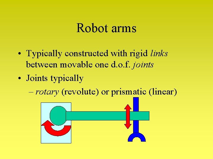
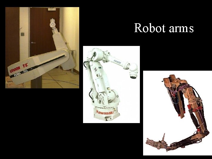
Robot arms • Typically constructed with rigid links between movable one d. o. f. joints • Joints typically – rotary (revolute) or prismatic (linear)
Robot arms
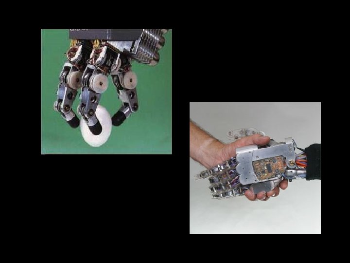
Robot arm end effectors • • Simple push or sweep Gripper – different shape, size or strength Vacuum cup, scoop, hook, magnetic Tools for specific purposes (drills, welding torch, spray head, scalpel, …) • Hand for variety of purposes
Actuation What produces the forces to move the effectors? Electrical: – DC motors (speed proportional to voltage – voltage varied by pulse width modulation) – Stepper motors (fixed move per pulse) Pressurised – Liquid: Hydraulics – Air: Pneumatics, air muscles Connected via transmission: system gears, brakes, valves, locks, springs…
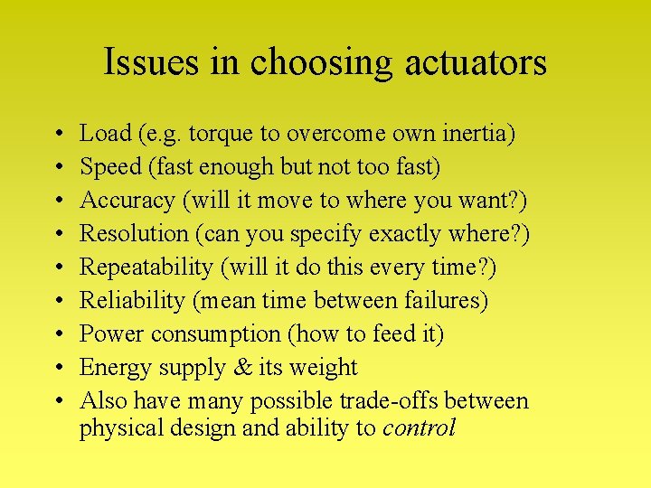
Issues in choosing actuators • • • Load (e. g. torque to overcome own inertia) Speed (fast enough but not too fast) Accuracy (will it move to where you want? ) Resolution (can you specify exactly where? ) Repeatability (will it do this every time? ) Reliability (mean time between failures) Power consumption (how to feed it) Energy supply & its weight Also have many possible trade-offs between physical design and ability to control
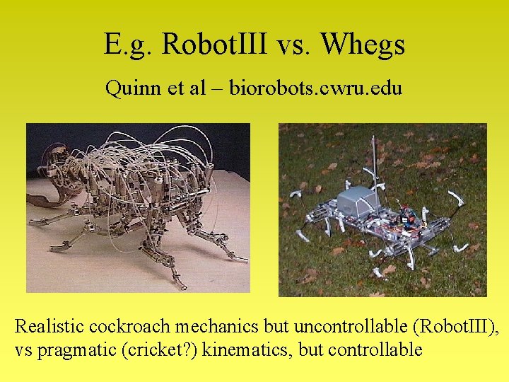
E. g. Robot. III vs. Whegs Quinn et al – biorobots. cwru. edu Realistic cockroach mechanics but uncontrollable (Robot. III), vs pragmatic (cricket? ) kinematics, but controllable
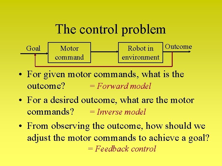
The control problem Goal Motor command Outcome Robot in environment • For given motor commands, what is the = Forward model outcome? • For a desired outcome, what are the motor = Inverse model commands? • From observing the outcome, how should we adjust the motor commands to achieve a goal? = Feedback control
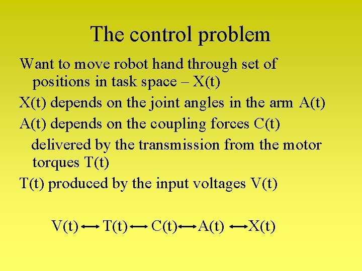
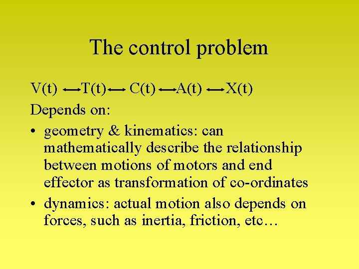
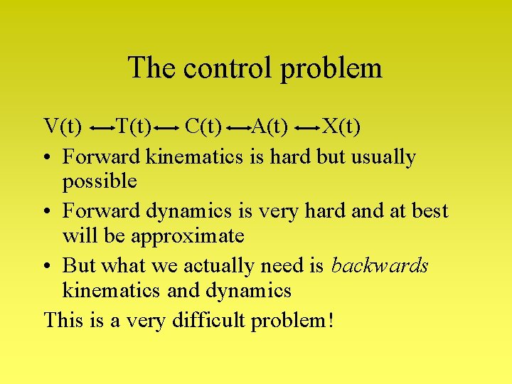
The control problem Want to move robot hand through set of positions in task space – X(t) depends on the joint angles in the arm A(t) depends on the coupling forces C(t) delivered by the transmission from the motor torques T(t) produced by the input voltages V(t) T(t) C(t) A(t) X(t)
The control problem V(t) T(t) C(t) A(t) X(t) Depends on: • geometry & kinematics: can mathematically describe the relationship between motions of motors and effector as transformation of co-ordinates • dynamics: actual motion also depends on forces, such as inertia, friction, etc…
The control problem V(t) T(t) C(t) A(t) X(t) • Forward kinematics is hard but usually possible • Forward dynamics is very hard and at best will be approximate • But what we actually need is backwards kinematics and dynamics This is a very difficult problem!
Summary • Some energy sources: electrical, hydralic, air, muscles, … • A variety of effectors: wheels, legs, tracks, fingers, tools, … • Degrees of Freedom and joints • Calculating control hard