ECE 683 Computer Network Design Analysis Note 5


- Slides: 50
ECE 683 Computer Network Design & Analysis Note 5: Peer-to-Peer Protocols 1
Outline • Peer-to-Peer Protocols and Service Models • Error Control (Detection and Correction) – Forward Error Control (FEC) – Error detection (3. 8) – Automatic Retransmission Request (ARQ) 2
Note 5: Peer-to-Peer Protocols and Data Link Control Peer-to-Peer Protocols and Service Models 3
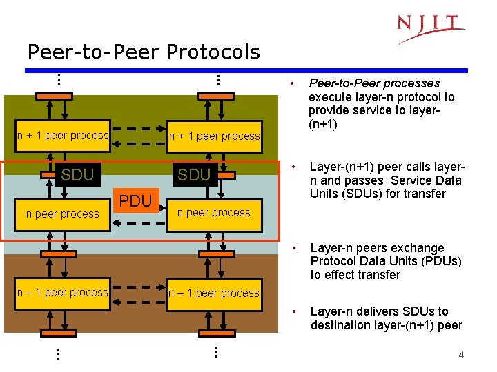
Peer-to-Peer Protocols n + 1 peer process SDU PDU • Layer-(n+1) peer calls layern and passes Service Data Units (SDUs) for transfer • Layer-n peers exchange Protocol Data Units (PDUs) to effect transfer • Layer-n delivers SDUs to destination layer-(n+1) peer n peer process n – 1 peer process Peer-to-Peer processes execute layer-n protocol to provide service to layer(n+1) n + 1 peer process SDU n peer process • 4
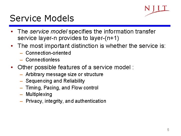
Service Models • The service model specifies the information transfer service layer-n provides to layer-(n+1) • The most important distinction is whether the service is: – Connection-oriented – Connectionless • Other possible features of a service model : – – – Arbitrary message size or structure Sequencing and Reliability Timing, Pacing, and Flow control Multiplexing Privacy, integrity, and authentication 5
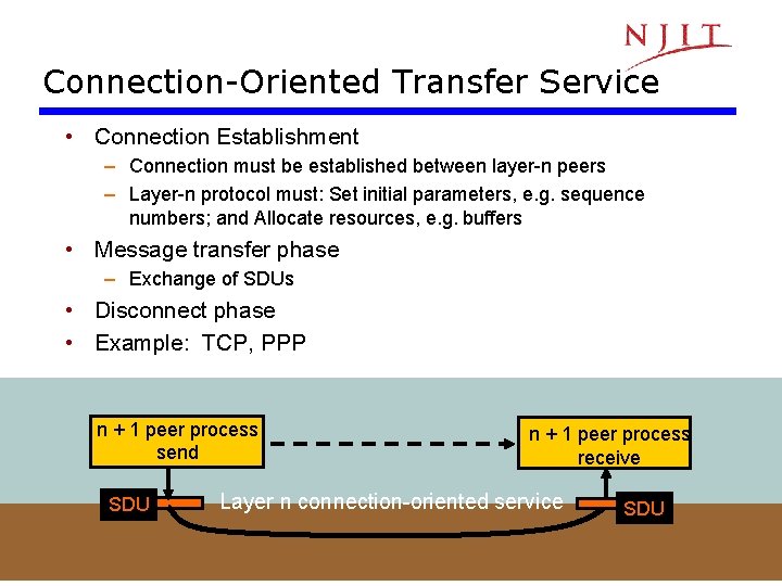
Connection-Oriented Transfer Service • Connection Establishment – Connection must be established between layer-n peers – Layer-n protocol must: Set initial parameters, e. g. sequence numbers; and Allocate resources, e. g. buffers • Message transfer phase – Exchange of SDUs • Disconnect phase • Example: TCP, PPP n + 1 peer process send SDU n + 1 peer process receive Layer n connection-oriented service SDU 6
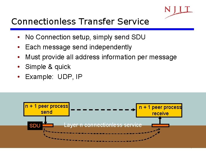
Connectionless Transfer Service • • • No Connection setup, simply send SDU Each message send independently Must provide all address information per message Simple & quick Example: UDP, IP n + 1 peer process send SDU n + 1 peer process receive Layer n connectionless service 7
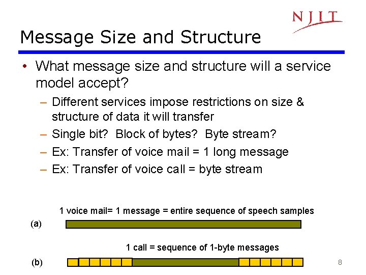
Message Size and Structure • What message size and structure will a service model accept? – Different services impose restrictions on size & structure of data it will transfer – Single bit? Block of bytes? Byte stream? – Ex: Transfer of voice mail = 1 long message – Ex: Transfer of voice call = byte stream 1 voice mail= 1 message = entire sequence of speech samples (a) 1 call = sequence of 1 -byte messages (b) 8
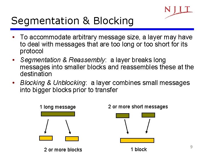
Segmentation & Blocking • To accommodate arbitrary message size, a layer may have to deal with messages that are too long or too short for its protocol • Segmentation & Reassembly: a layer breaks long messages into smaller blocks and reassembles these at the destination • Blocking & Unblocking: a layer combines small messages into bigger blocks prior to transfer 1 long message 2 or more blocks 2 or more short messages 1 block 9
Reliability & Sequencing • Reliability: Are messages or information stream delivered error-free and without loss or duplication? • Sequencing: Are messages or information stream delivered in order? • ARQ protocols combine error detection, retransmission, and sequence numbering to provide reliability & sequencing • Examples: TCP and HDLC 10
Pacing and Flow Control • Messages can be lost if receiving system does not have sufficient buffering to store arriving messages • Pacing & Flow Control provide backpressure mechanisms that control transfer according to availability of buffers at the destination • Examples: TCP and HDLC 11
Timing • Applications involving voice and video generate units of information that are related temporally • Destination application must reconstruct temporal relation in voice/video units • Network transfer introduces delay & jitter • Timing Recovery protocols use timestamps & sequence numbering to control the delay & jitter in delivered information • Examples: RTP & associated protocols in Voice over IP 12
Multiplexing • Multiplexing enables multiple layer-(n+1) users to share a layer-n service • A multiplexing tag is required to identify specific users at the destination • Examples: UDP, IP 13
Privacy, Integrity, & Authentication • Privacy: ensuring that information transferred cannot be read by others • Integrity: ensuring that information is not altered during transfer • Authentication: verifying that sender and/or receiver are who they claim to be • Security protocols provide these services and are discussed in Chapter 11 • Examples: IPSec, SSL 14
End-to-End vs. Hop-by-Hop • A service feature can be provided by implementing a protocol – end-to-end across the entire network – across every hop in the network • Example: – Perform error control at every hop in the network or only between the source and destination? – Perform flow control between every hop in the network or only between source & destination? • We next consider the tradeoffs between the two approaches 15
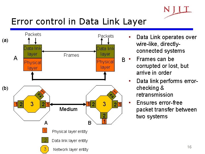
Error control in Data Link Layer Packets (a) A Data link layer Frames Physical layer 12 3 2 2 1 1 (b) • Data Link operates over wire-like, directly. Data link connected systems layer B • Frames can be Physical corrupted or lost, but layer arrive in order • Data link performs errorchecking & retransmission 12 3 2 1 • Ensures error-free packet transfer between 2 two systems 21 Medium B A 1 Physical layer entity 2 Data link layer entity 3 Network layer entity 1 16
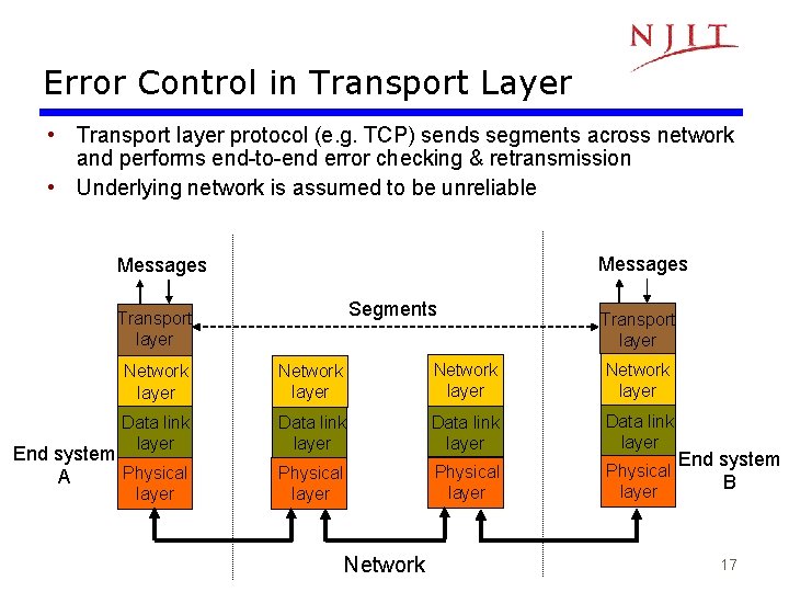
Error Control in Transport Layer • Transport layer protocol (e. g. TCP) sends segments across network and performs end-to-end error checking & retransmission • Underlying network is assumed to be unreliable Messages Segments Transport layer Network layer Data link layer Physical layer End system Physical A Network End system B 17
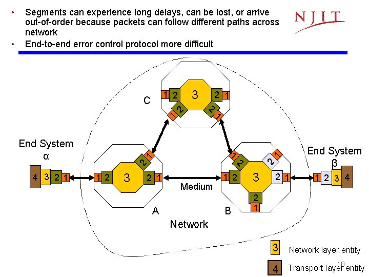
3 End System α 1 1 4 3 21 12 3 2 1 Medium A 2 End System β 1 2 2 1 2 C 1 • Segments can experience long delays, can be lost, or arrive out-of-order because packets can follow different paths across network End-to-end error control protocol more difficult 2 • 1 2 3 B 2 1 1 2 3 4 Network 3 Network layer entity 4 Transport layer entity 18
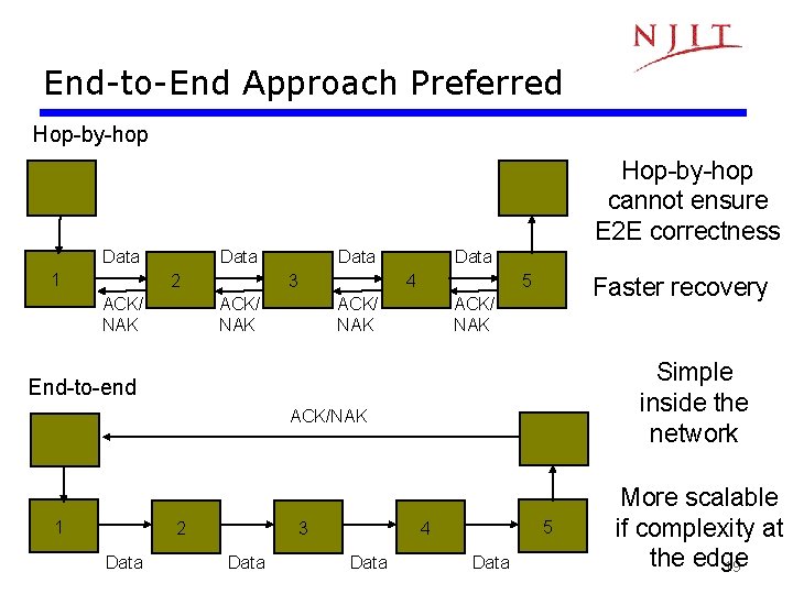
End-to-End Approach Preferred Hop-by-hop cannot ensure E 2 E correctness Data 1 Data 2 ACK/ NAK Data 3 Data 4 ACK/ NAK 5 ACK/ NAK Faster recovery ACK/ NAK Simple inside the network End-to-end ACK/NAK 1 2 Data 3 Data 5 4 Data More scalable if complexity at the edge 19
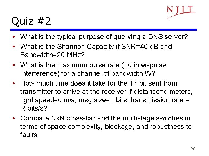
Quiz #2 • What is the typical purpose of querying a DNS server? • What is the Shannon Capacity if SNR=40 d. B and Bandwidth=20 MHz? • What is the maximum pulse rate (no inter-pulse interference) for a channel of bandwidth W? • How much time does it take for the 1 st bit sent from transmitter to arrive at the receiver if distance=d meters, light speed=c m/s, msg size=L bits, transmission rate = R bits/s? • Compare Nx. N cross-bar and the multistage switches in terms of space complexity, blockage, and robustness to faults. 20
Note 5: Peer-to-Peer Protocols and Data Link Control Error Control: Detection & Correction 21
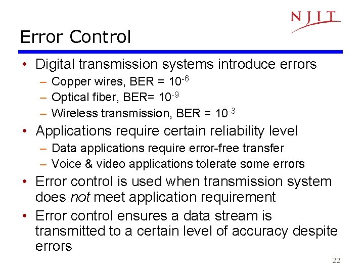
Error Control • Digital transmission systems introduce errors – Copper wires, BER = 10 -6 – Optical fiber, BER= 10 -9 – Wireless transmission, BER = 10 -3 • Applications require certain reliability level – Data applications require error-free transfer – Voice & video applications tolerate some errors • Error control is used when transmission system does not meet application requirement • Error control ensures a data stream is transmitted to a certain level of accuracy despite errors 22
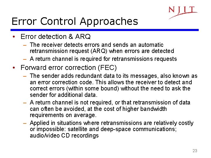
Error Control Approaches • Error detection & ARQ – The receiver detects errors and sends an automatic retransmission request (ARQ) when errors are detected – A return channel is required for retransmissions requests • Forward error correction (FEC) – The sender adds redundant data to its messages, also known as an error correction code. This allows the receiver to detect and correct errors (within some bound) without the need to ask the sender for additional data. – A return channel is not required, or that retransmission of data can often be avoided, at the cost of higher bandwidth requirements on average. – Applied in situations where retransmissions are relatively costly or impossible: satellite and deep-space communications; audio/video CD recordings 23
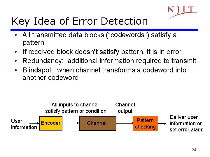
Key Idea of Error Detection • All transmitted data blocks (“codewords”) satisfy a pattern • If received block doesn’t satisfy pattern, it is in error • Redundancy: additional information required to transmit • Blindspot: when channel transforms a codeword into another codeword All inputs to channel satisfy pattern or condition User Encoder information Channel output Pattern checking Deliver user information or set error alarm 24
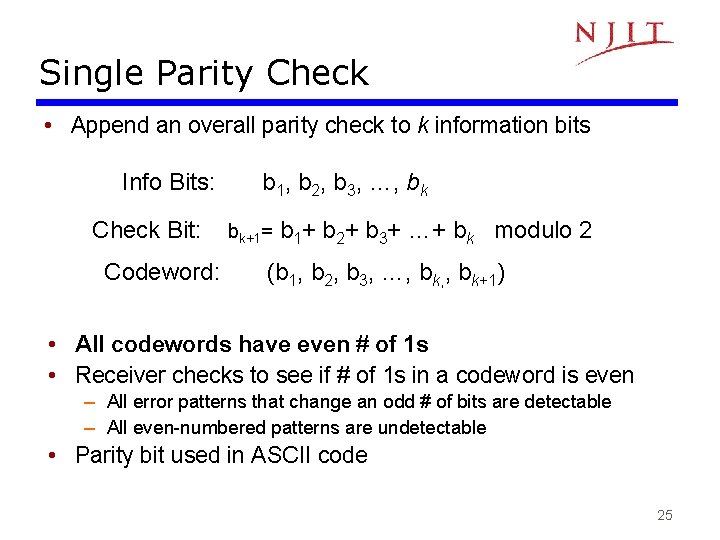
Single Parity Check • Append an overall parity check to k information bits Info Bits: Check Bit: Codeword: b 1, b 2, b 3, …, bk bk+1= b 1+ b 2+ b 3+ …+ bk modulo 2 (b 1, b 2, b 3, …, bk, , bk+1) • All codewords have even # of 1 s • Receiver checks to see if # of 1 s in a codeword is even – All error patterns that change an odd # of bits are detectable – All even-numbered patterns are undetectable • Parity bit used in ASCII code 25
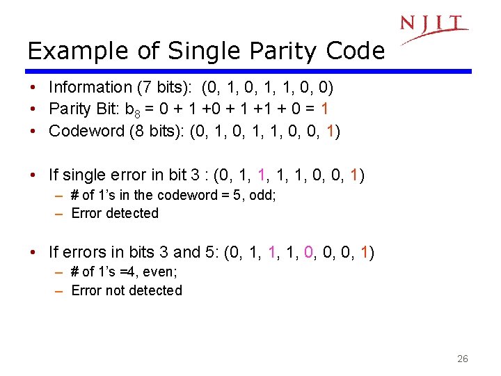
Example of Single Parity Code • Information (7 bits): (0, 1, 1, 0, 0) • Parity Bit: b 8 = 0 + 1 +1 + 0 = 1 • Codeword (8 bits): (0, 1, 1, 0, 0, 1) • If single error in bit 3 : (0, 1, 1, 0, 0, 1) – # of 1’s in the codeword = 5, odd; – Error detected • If errors in bits 3 and 5: (0, 1, 1, 1, 0, 0, 0, 1) – # of 1’s =4, even; – Error not detected 26
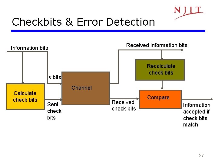
Checkbits & Error Detection Received information bits Information bits Recalculate check bits Calculate check bits Channel Sent check bits Received check bits Compare Information accepted if check bits match 27
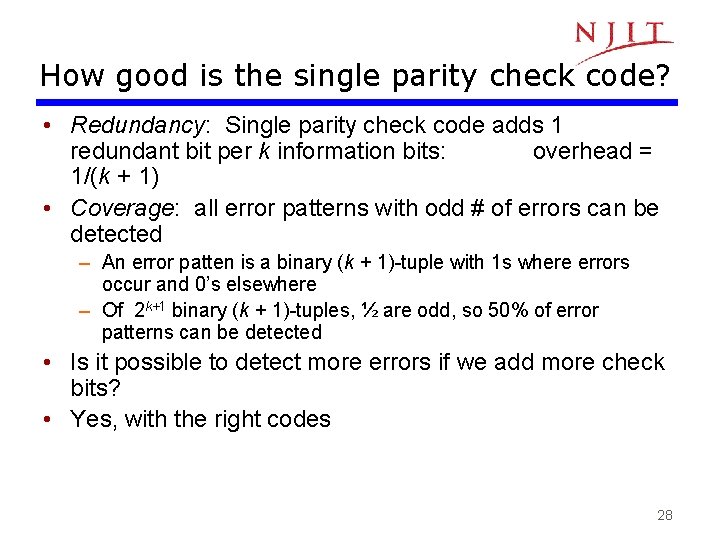
How good is the single parity check code? • Redundancy: Single parity check code adds 1 redundant bit per k information bits: overhead = 1/(k + 1) • Coverage: all error patterns with odd # of errors can be detected – An error patten is a binary (k + 1)-tuple with 1 s where errors occur and 0’s elsewhere – Of 2 k+1 binary (k + 1)-tuples, ½ are odd, so 50% of error patterns can be detected • Is it possible to detect more errors if we add more check bits? • Yes, with the right codes 28
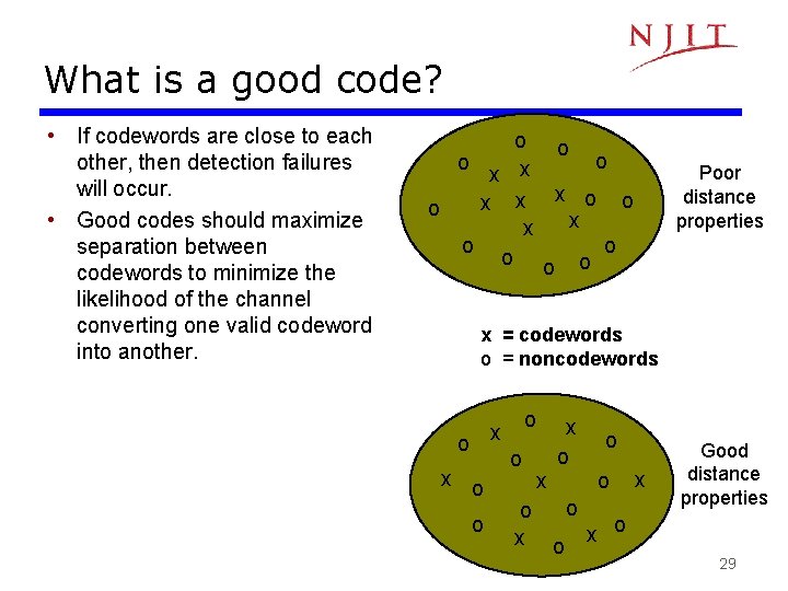
What is a good code? • If codewords are close to each other, then detection failures will occur. • Good codes should maximize separation between codewords to minimize the likelihood of the channel converting one valid codeword into another. o o x x x o o o Poor distance properties x = codewords o = noncodewords o x x o o o x x Good distance properties 29
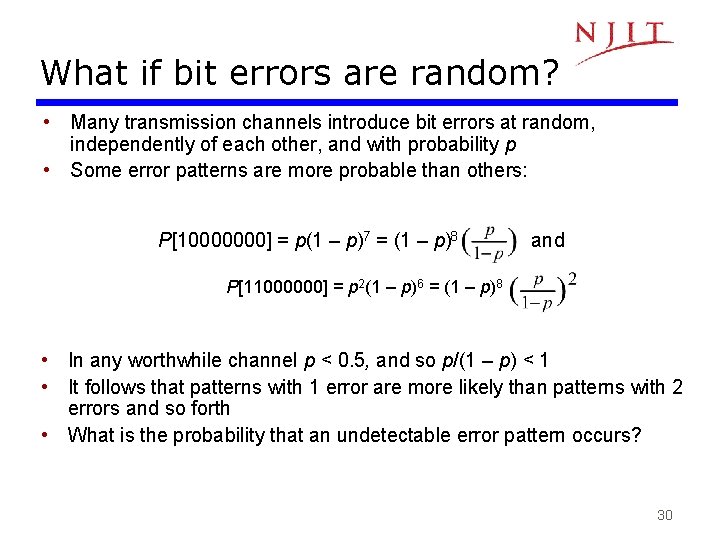
What if bit errors are random? • Many transmission channels introduce bit errors at random, independently of each other, and with probability p • Some error patterns are more probable than others: P[10000000] = p(1 – p)7 = (1 – p)8 and P[11000000] = p 2(1 – p)6 = (1 – p)8 • In any worthwhile channel p < 0. 5, and so p/(1 – p) < 1 • It follows that patterns with 1 error are more likely than patterns with 2 errors and so forth • What is the probability that an undetectable error pattern occurs? 30
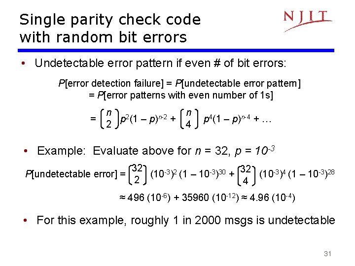
Single parity check code with random bit errors • Undetectable error pattern if even # of bit errors: P[error detection failure] = P[undetectable error pattern] = P[error patterns with even number of 1 s] = n 2 p (1 – p)n-2 + 2 n 4 p 4(1 – p)n-4 + … • Example: Evaluate above for n = 32, p = 10 -3 P[undetectable error] = 32 32 (10 -3)2 (1 – 10 -3)30 + (10 -3)4 (1 – 10 -3)28 2 4 ≈ 496 (10 -6) + 35960 (10 -12) ≈ 4. 96 (10 -4) • For this example, roughly 1 in 2000 msgs is undetectable 31
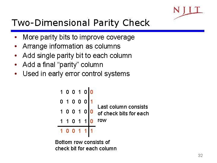
Two-Dimensional Parity Check • • • More parity bits to improve coverage Arrange information as columns Add single parity bit to each column Add a final “parity” column Used in early error control systems 1 0 0 0 1 Last column consists 1 0 0 of check bits for each 1 1 0 row 1 0 0 1 1 1 Bottom row consists of check bit for each column 32
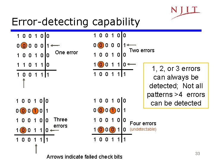
Error-detecting capability 1 0 0 0 0 0 0 0 1 1 0 0 One error 1 0 0 1 1 0 0 1 1 1 1 0 0 1 0 0 0 1 1 0 0 Three errors 1 0 0 1 0 0 1 1 1 1 0 0 0 1 0 Arrows indicate failed check bits Two errors 1, 2, or 3 errors can always be detected; Not all patterns >4 errors can be detected Four errors (undetectable) 33
Other Error Detection Codes • • • Many applications require very low error rate Need codes that detect the vast majority of errors Single parity check codes do not detect enough errors Two-dimensional codes require too many check bits The following error detecting codes used in practice: – Internet Check Sums – CRC Polynomial Codes 34
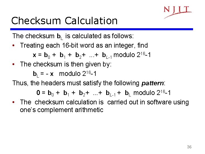
Internet Checksum • Several Internet protocols (e. g. IP, TCP, UDP) use check bits to detect errors in the IP header (or in the header and data for TCP/UDP) • A checksum is calculated for header contents and included in a special field. • Checksum recalculated at every router, so algorithm selected for ease of implementation in software • Let header consist of L, 16 -bit words, b 0, b 1, b 2, . . . , b. L-1 • The algorithm appends a 16 -bit checksum b. L 35
Checksum Calculation The checksum b. L is calculated as follows: • Treating each 16 -bit word as an integer, find x = b 0 + b 1 + b 2+. . . + b. L-1 modulo 216 -1 • The checksum is then given by: b. L = - x modulo 216 -1 Thus, the headers must satisfy the following pattern: 0 = b 0 + b 1 + b 2+. . . + b. L-1 + b. L modulo 216 -1 • The checksum calculation is carried out in software using one’s complement arithmetic 36
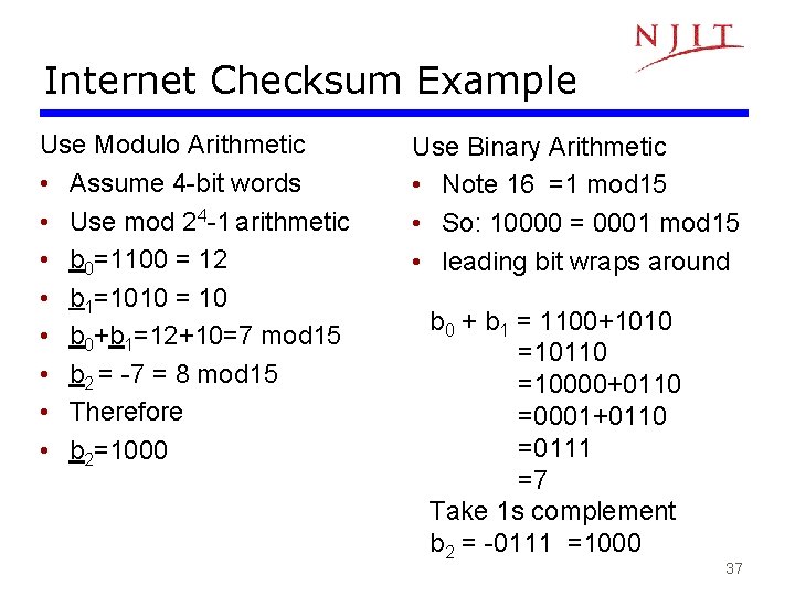
Internet Checksum Example Use Modulo Arithmetic • Assume 4 -bit words • Use mod 24 -1 arithmetic • b 0=1100 = 12 • b 1=1010 = 10 • b 0+b 1=12+10=7 mod 15 • b 2 = -7 = 8 mod 15 • Therefore • b 2=1000 Use Binary Arithmetic • Note 16 =1 mod 15 • So: 10000 = 0001 mod 15 • leading bit wraps around b 0 + b 1 = 1100+1010 =10110 =10000+0110 =0001+0110 =0111 =7 Take 1 s complement b 2 = -0111 =1000 37
Polynomial Codes • • Polynomials instead of vectors for codewords Polynomial arithmetic instead of checksums Implemented using shift-register circuits Also called cyclic redundancy check (CRC) codes • Most data communications standards use polynomial codes for error detection • Polynomial codes also basis for powerful errorcorrection methods 38
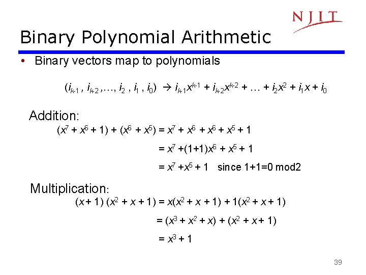
Binary Polynomial Arithmetic • Binary vectors map to polynomials (ik-1 , ik-2 , …, i 2 , i 1 , i 0) ik-1 xk-1 + ik-2 xk-2 + … + i 2 x 2 + i 1 x + i 0 Addition: (x 7 + x 6 + 1) + (x 6 + x 5) = x 7 + x 6 + x 5 + 1 = x 7 +(1+1)x 6 + x 5 + 1 = x 7 +x 5 + 1 since 1+1=0 mod 2 Multiplication: (x + 1) (x 2 + x + 1) = x(x 2 + x + 1) + 1(x 2 + x + 1) = (x 3 + x 2 + x) + (x 2 + x + 1) = x 3 + 1 39
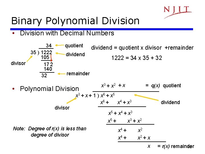
Binary Polynomial Division • Division with Decimal Numbers 34 35 ) 1222 105 divisor 17 2 140 32 quotient dividend = quotient x divisor +remainder 1222 = 34 x 35 + 32 remainder • Polynomial Division divisor x 3 + x 2 + x = q(x) quotient x 3 + x + 1 ) x 6 + x 5 x 6 + x 4 + x 3 Note: Degree of r(x) is less than degree of divisor dividend x 5 + x 4 + x 3 x 5 + x 3 + x 2 x 4 + x 2 + x x = r(x) remainder 40
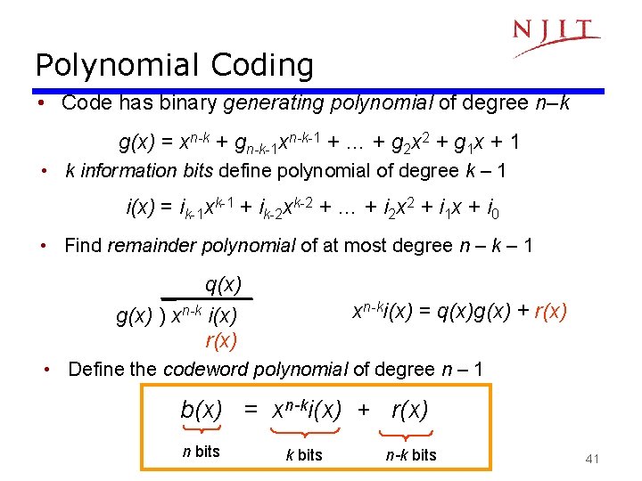
Polynomial Coding • Code has binary generating polynomial of degree n–k g(x) = xn-k + gn-k-1 xn-k-1 + … + g 2 x 2 + g 1 x + 1 • k information bits define polynomial of degree k – 1 i(x) = ik-1 xk-1 + ik-2 xk-2 + … + i 2 x 2 + i 1 x + i 0 • Find remainder polynomial of at most degree n – k – 1 q(x) g(x) ) xn-k i(x) r(x) xn-ki(x) = q(x)g(x) + r(x) • Define the codeword polynomial of degree n – 1 b(x) = xn-ki(x) + r(x) n bits k bits n-k bits 41
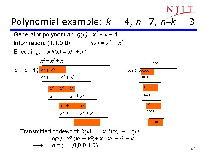
Polynomial example: k = 4, n=7, n–k = 3 Generator polynomial: g(x)= x 3 + x + 1 Information: (1, 1, 0, 0) i(x) = x 3 + x 2 Encoding: x 3 i(x) = x 6 + x 5 x 3 + x 2 + x x 3 + x + 1 ) x 6 + x 5 x 6 + 1011 ) 1100000 1011 x 4 + x 3 1110 1011 x 5 + x 4 + x 3 x 5 + x 3 + x 2 x 4 + 1110 x 2 + x x Transmitted codeword: b(x) = xn-ki(x) + r(x) b(x) =x 3 (x 3 + x 2)+ x= x 6 + x 5 + x b = (1, 1, 0, 0, 0, 1, 0) 1010 1011 010 42
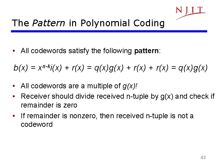
The Pattern in Polynomial Coding • All codewords satisfy the following pattern: b(x) = xn-ki(x) + r(x) = q(x)g(x) • All codewords are a multiple of g(x)! • Receiver should divide received n-tuple by g(x) and check if remainder is zero • If remainder is nonzero, then received n-tuple is not a codeword 43
Undetectable error patterns (Transmitter) b(x) (Receiver) + R(x)=b(x)+e(x) (Channel) e(x) Error polynomial • e(x) has 1 s in error locations & 0 s elsewhere • Receiver divides the received polynomial R(x) by g(x) • Blindspot: If e(x) is a multiple of g(x), that is, e(x) is a nonzero codeword, then R(x) = b(x) + e(x) = q(x)g(x) + q’(x)g(x) • Choose the generator polynomial so that selected error patterns can be detected. 44
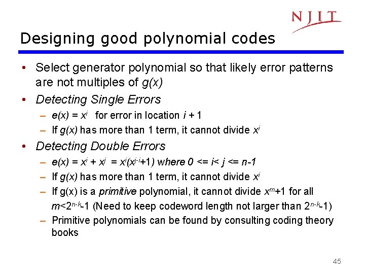
Designing good polynomial codes • Select generator polynomial so that likely error patterns are not multiples of g(x) • Detecting Single Errors – e(x) = xi for error in location i + 1 – If g(x) has more than 1 term, it cannot divide xi • Detecting Double Errors – e(x) = xi + xj = xi(xj-i+1) where 0 <= i< j <= n-1 – If g(x) has more than 1 term, it cannot divide xi – If g(x) is a primitive polynomial, it cannot divide xm+1 for all m<2 n-k-1 (Need to keep codeword length not larger than 2 n-k-1) – Primitive polynomials can be found by consulting coding theory books 45
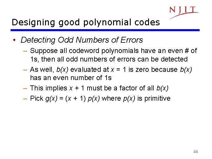
Designing good polynomial codes • Detecting Odd Numbers of Errors – Suppose all codeword polynomials have an even # of 1 s, then all odd numbers of errors can be detected – As well, b(x) evaluated at x = 1 is zero because b(x) has an even number of 1 s – This implies x + 1 must be a factor of all b(x) – Pick g(x) = (x + 1) p(x) where p(x) is primitive 46
Detecting error bursts 47
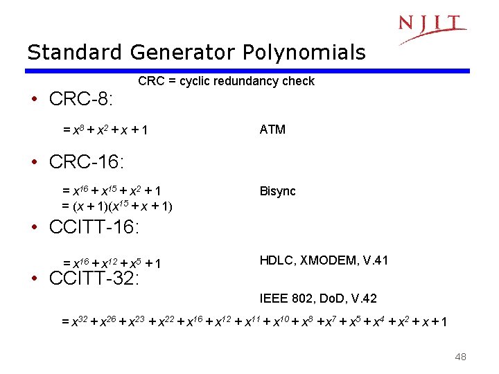
Standard Generator Polynomials • CRC-8: CRC = cyclic redundancy check = x 8 + x 2 + x + 1 ATM • CRC-16: = x 16 + x 15 + x 2 + 1 = (x + 1)(x 15 + x + 1) Bisync • CCITT-16: = x 16 + x 12 + x 5 + 1 • CCITT-32: HDLC, XMODEM, V. 41 IEEE 802, Do. D, V. 42 = x 32 + x 26 + x 23 + x 22 + x 16 + x 12 + x 11 + x 10 + x 8 + x 7 + x 5 + x 4 + x 2 + x + 1 48
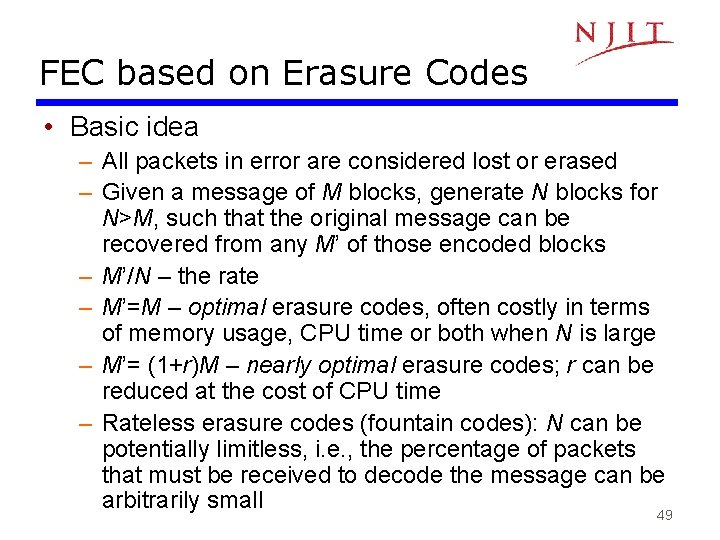
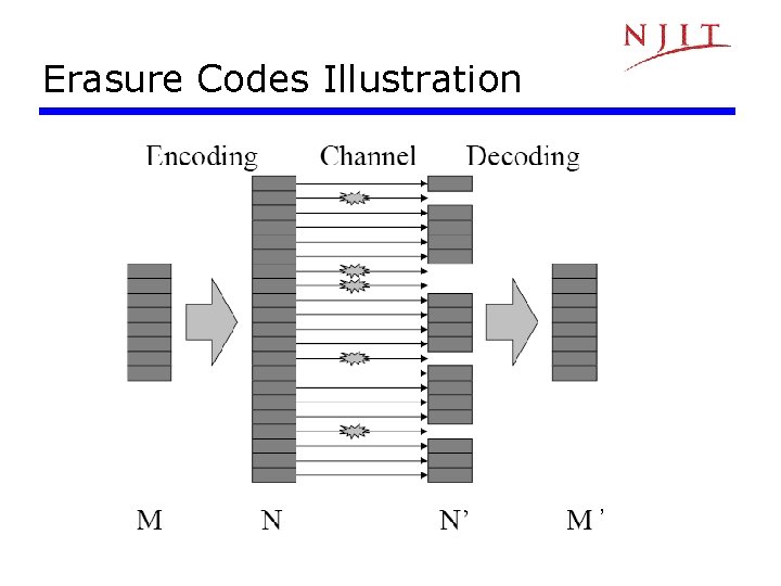
FEC based on Erasure Codes • Basic idea – All packets in error are considered lost or erased – Given a message of M blocks, generate N blocks for N>M, such that the original message can be recovered from any M’ of those encoded blocks – M’/N – the rate – M’=M – optimal erasure codes, often costly in terms of memory usage, CPU time or both when N is large – M’= (1+r)M – nearly optimal erasure codes; r can be reduced at the cost of CPU time – Rateless erasure codes (fountain codes): N can be potentially limitless, i. e. , the percentage of packets that must be received to decode the message can be arbitrarily small 49
Erasure Codes Illustration ’