DTL M Comunian M Eshraqi Outline DTL Design


 Points defined at LNL meeting")
 Points defined at LNL meeting")
![DTL Layout Tank Length [m] Cells Total Power [k. W] Max Kp Final Energy](https://slidetodoc.com/presentation_image_h2/854df11145a9455b091866cb97a8a928/image-6.jpg "DTL Layout Tank Length [m] Cells Total Power [k. W] Max Kp Final Energy")


- Slides: 30
DTL M. Comunian M. Eshraqi
Outline • DTL Design. • Beam Dynamics. • Errors Study.
DTL Design • • • Input energy of 3 Me. V. Maximum integrated field of 3. 8 T for PMQ. Currents: 50 m. A. FODO PMQ Lattice. PMQ law almost equipartitioned. Input RMS emittance Tr. / Long. 0. 22/0. 28 mmmrad
Summary of boundary parameters for nominal DTL design (1) Points defined at LNL meeting 9 -10/7/2012 Parameter Final energy Maximum RF power/tank PMQ law Surface E field limit Tank Length Value or Range 75 Me. V to 85 Me. V 2. 15 MW Including 1. 25 margins. Equipartitioned At 3 Me. V: 1. 39 kp Absolute max: of 1. 6 kp <8 m E 0 Synch. phase 2. 8 to 5. 0 MV/m N° of Tank Bore radius 4 or 5 Intertank space Notes -35° to -20° Tank 1 and 2=10 mm; Tank 3=1. 1 mm; From Tank 4= 1. 2 mm 1 βλ “Moretti” limit for 70 T/m PMQ Mechanical modules of max 2 meters. Linearly ramped Keep large longitudinal acceptance
Summary of boundary parameters for nominal DTL design (2) Points defined at LNL meeting 9 -10/7/2012 Parameter Losses Longitudinal phase advance Value or Range Notes <1 W/m Avoid radiation damages of PMQs Tune depression RMS emittance increasing 99% emittance over RMS emittance Final longitudinal phase advance Final transverse phase advance > 0. 4 for all planes Phase change for intertank longitudinal matching. E 0 error Phase error Continuous along the DTL Sensitivity to mismatch Long: < 40% Transv: < 20% < 10 Limit on Halo 18°/m ± 1°/m Matching with SC linac 21°/m ± 1°/m Matching with SC linac < 5° RF design ± 2% RF design ± 4° RF design
DTL Layout Tank Length [m] Cells Total Power [k. W] Max Kp Final Energy [Me. V] E 0 [MV/m] R bore [mm] Flat Phase length [deg] [mm] 1 7. 953 66 2061 1. 42 21. 5 2. 8 ÷ 3. 2 10 0. 7 -35 ÷ -24 2 7. 628 36 2117 1. 43 41. 1 3. 16 10 0. 5 -24 3 7. 762 29 2099 1. 40 60. 0 3. 16 11 0. 5 -24 4 7. 724 25 2076 1. 36 77. 7 3. 16 12 0. 4 -24
Design Law on E 0 phase and surface field
GEN DTL solution on design constrain
Ratio Bore/RMS from 9 to 6 Max size Gaussian 6σ
Beam Density with Input distribution Gaussian 6σ
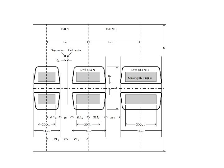
Intertank space: 1 bl • Each tank begins with a current monitor. • Matching by using 2 PMQ at tank end and 2 PMQ at tank begin and changing the phases with max of +/- 5°. SNS Tank 1 -Tank 2: 1 bl
Intertank space: 1 bl F O D O F bl bl bl From first to second tank=179. 022 mm O
Equipartitioning all along the DTL High order resonances Gradient High Gradient Low
Phase advance at zero current Input: k 0 T=290 °/m k 0 L=240 °/m Output: k 0 T=22 °/m k 0 L=19 °/m
RMS Emittance along the DTL Uniform: ET/E 0 T=1. 05 EL/E 0 L=1. 09 99% Emittance along the DTL Gaussian: ET/E 0 T=1. 14 EL/E 0 L=1. 18
Max transverse acceptance=11. 6 mmmrad norm. Max Longitudinal acceptance=10 deg. Me. V Acc/RMS Ratio: Transverse=53 Longitudinal=91
Error study on the DTL • All errors apply together with a Uniform input beam distribution with added a “halo” distribution with 3 times the emittance and 3σ as gaussian size distribution, 0. 625% of the beam as halo, i. e. 1 k. W. • 100 random DTL generated. • 1. 6*10^5 particles i. e. 1 W for particle at 50 m. A, 80 Me. V. • Separate X, Y Steerer used with max force of 1. 6 m. T*m.
Gaussian 6σ Uniform+Halo With Uniform+Halo is increased the number of particles at large amplitude
Steerers on FODO Lattice • Using the empty space on the lattice it has been put steerers X or Y • 4 Steerers and 2 BPM for each tank. • Max steerer strength of 1. 6 m. T*m. • Diagnostics BPM with 0. 05 mm accuracy. SNS Steerer, max 1. 9 m. T*m
DTL BI layout Tank 1 BLM Tank 2 BLM Beam FC FC WS WS 0 Tank 3 BLM Tank 4 WS FC FC Symbol Name DTL Tank Wire Scanner BLM Beam Loss Monitor Energy degrader Number of units Symbol 4 3 6 FC Name Number of units BPM / Phase detector in DT Current Monitor (Toroid) Faraday cup (Beam stop) 8 4 4 3 Benjamin Cheymol
Steerers Position Element # Sx Sy BPM Tank 1 7 10 23 26 62 67 Tank 2 80 83 92 95 106 111 Tank 3 120 123 132 135 142 147 Tank 4 155 158 167 169 178 183
Errors results on E 0 without correction Steerers Step 1 Maximum E 0 shake cell by cell of ± 5%
E 0 Errors of +/- 2% cell by cell. Total=0. 7 Watts E 0 Errors of +/- 5% cell by cell. Total=1. 77 Watts
Errors results on ϕs without correction Steerers Step 1 Maximum ϕs shake cell by cell of ± 5°
ϕs Errors of +/- 2° cell by cell. Total=1. 9 Watts ϕs Errors of +/- 5° cell by cell. Total=2. 45 Watts
Errors results on quad without correction Steerers Step 1 Maximum Quad shake of X, Y ± 0. 2 mm; ± 1°; ± 1% Quad shake of X, Y ± 0. 1 mm; ± 0. 5°; ± 0. 5% Max emittance growth=40% Total loss=42 Watts
Errors results on quad with correction Steerers Step 1 Maximum Quad shake of X, Y ± 0. 2 mm; ± 1°; ± 1% Quad shake of X, Y ± 0. 1 mm; ± 0. 5°; ± 0. 5% Max emittance growth=20% Total loss=2 Watts
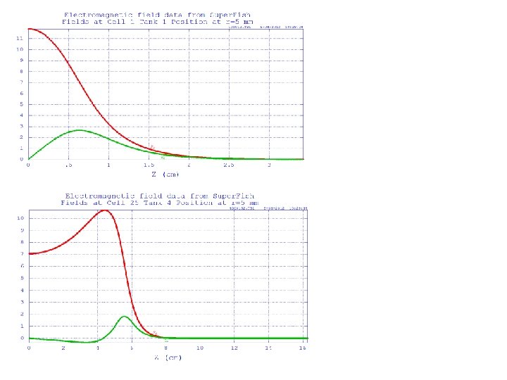
Conclusion • Complete definition of DTL parameters. • Solution with 4 Tanks. • With the steerers the losses are reduced by a factor 10 and the emittance growth by a factor 2. • Max error on E 0 shape +/- 2%. • Max error on Phase +/- 2°. • Max quad error X, Y ± 0. 2 mm; ± 1°; ± 1%. • The quad error are reduces due to the steerers: doubled the CERN specifications. • Beam Dynamics with Super. Fish full fields map and/or other simulation code. • Design with the real quadrupoles family. • Still possible further DTL optimizations?