Computer Graphics V Semester Unit 4 Illumination and


 model: determine the color of a surface point")
 Model • To model the interaction of light with surfaces to determine")


 • The light that is the result from the light")


 N")


")

![Open. GL Materials GLfloat white 8[] = {. 8, 1. }, white 2 =](https://slidetodoc.com/presentation_image_h/2ed616508f103832d16b71812fdc266e/image-23.jpg "Open. GL Materials GLfloat white 8[] = {. 8, 1. }, white 2 =")
![Open. GL Lighting GLfloat white[] = {1. , 1. }; GLfloat light 0_position[] =](https://slidetodoc.com/presentation_image_h/2ed616508f103832d16b71812fdc266e/image-24.jpg "Open. GL Lighting GLfloat white[] = {1. , 1. }; GLfloat light 0_position[] =")
 § Compute illumination at any")


 of point P")


- Slides: 41
Computer Graphics V - Semester Unit – 4 Illumination and shading K. A. Dhamotharan, Assistant Professor ( Senior Grade)
Illumination and Shading
Illumination Vs. Shading § Illumination (lighting) model: determine the color of a surface point by simulating some light attributes. § Shading model: applies the illumination models at a set of points and colors the whole image.
Illumination (Lighting) Model • To model the interaction of light with surfaces to determine the final color & brightness of the surface – Global illumination – Local illumination
Global Illumination • Global Illumination models: take into account the interaction of light from all the surfaces in the scene.
Local illumination • Only consider the light, the observer position, and the object material properties
Basic Illumination Model • Simple and fast method for calculating surface intensity at a given point • Lighting calculation are based on: – The background lighting conditions – The light source specification: color, position
Ambient light (background light) • The light that is the result from the light reflecting off other surfaces in the environment • A general level of brightness for a scene that is independent of the light positions or surface directions -> ambient light • Has no direction • Each light source has an ambient light contribution, Ia • For a given surface, we can specify how much ambient light the surface can reflect using an ambient reflection coefficient : Ka (0 < Ka < 1)
Ambient Light • So the amount of light that the surface reflect is therefore Iamb = Ka * Ia
Diffuse Light • The illumination that a surface receives from a light source and reflects equally in all directions • This type of reflection is called Lambertian Reflection (thus, Lambertian surfaces) • The brightness of the surface is indepenent of the observer position (since the light is reflected in all direction equally)
Lambert’s Law • How much light the surface receives from a light source depends on the angle between its angle and the vector from the surface point to the light (light vector) • Lambert’s law: the radiant energy ’Id’ from a small surface da for a given light source is: Id = IL * cos(q) IL : the intensity of the light source q is the angle between the surface normal (N) and light vector (L)
The Diffuse Component • Surface’s material property: assuming that the surface can reflect Kd (0<Kd<1), diffuse reflection coefficient) amount of diffuse light: Idiff = Kd * IL * cos(q) If N and L are normalized, cos(q) = N*L Idiff = Kd * IL * (N*L) • The total diffuse reflection = ambient + diffuse Idiff = Ka * Ia + Kd * IL * (N*L)
Examples Sphere diffusely lighted from various angles !
Specular Light § These are the bright spots on objects (such as polished metal, apple. . . ) § Light reflected from the surface unequally to all directions. § The result of near total reflection of the incident light in a concentrated region around the specular reflection angle
Phong’s Model for Specular • How much reflection light you can see depends on where you are
Phong Illumination Curves Specular exponents are much larger than 1; Values of 100 are not uncommon. : glossiness, rate of falloff
Specular Highlights • Shiny surfaces change appearance when viewpoint is changed • Specularities are caused by microscopically smooth surfaces. • A mirror is a perfect specular reflector
Reflected Ray N L How to calculate R? R + L = 2(N*L) N R f f a V R = 2(N*L) N - L 2 N(N • L) L N(N • L) f Project L onto N L L f Double length of vector R = 2 N(N • L) - L f f Subtract L
Half Vector • An alternative way of computing phong lighting is: Is = ks * Is * (N*H)n • H (halfway vector): halfway between V and L: (V+L)/2 L • Fuzzier highlight N H V
Phong Illumination Moving Light Change n
Putting It All Together • Single Light (white light source)
Multiple Light Source • IL: light intensity • For multiple light sources – Repeat the diffuse and specular calculations for each light source – Add the components from all light sources – The ambient term contributes only once • The different reflectance coefficients can differ. – Simple “metal”: ks and kd share material color, – Simple plastic: ks is white • Remember, when cosine is negative lighting term is zero!
Open. GL Materials GLfloat white 8[] = {. 8, 1. }, white 2 = {. 2, 1. }, black={0. , 0. }; GLfloat mat_shininess[] = {50. }; /* Phong exponent */ gl. Materialfv( GL_FRONT_AND_BACK, GL_AMBIENT, black); gl. Materialfv( GL_FRONT_AND_BACK, GL_DIFFUSE, white 8); gl. Materialfv( GL_FRONT_AND_BACK, GL_SPECULAR, white 2); gl. Materialfv( GL_FRONT_AND_BACK, GL_SHININESS, mat_shininess);
Open. GL Lighting GLfloat white[] = {1. , 1. }; GLfloat light 0_position[] = {1. , 5. , 0. }; /* directional light (w=0) */ gl. Lightfv(GL_LIGHT 0, GL_POSITION, light 0_position); gl. Lightfv(GL_LIGHT 0, GL_DIFFUSE, white); gl. Lightfv(GL_LIGHT 0, GL_SPECULAR, white); gl. Enable(GL_LIGHT 0); gl. Enable(GL_NORMALIZE); /* normalize normal vectors */ gl. Light. Modeli(GL_LIGHT_MODEL_TWO_SIDE, GL_TRUE); /* two-sided lighting*/ gl. Enable(GL_LIGHTING);
Shading Models for Polygons § Constant Shading (flat shading) § Compute illumination at any one point on the surface. Use face or one normal from a pair of edges. Good for far away light and viewer or if facets approximate surface well. § Per-Pixel Shading § Compute illumination at every point on the surface. § Interpolated Shading § Compute illumination at vertices and interpolate color
Constant Shading • Compute illumination only at one point on the surface • Okay to use if all of the following are true – The object is not a curved (smooth) surface (e. g. a polyhedron object) – The light source is very far away (so N. L does not change much across a polygon) – The eye is very far away (so V. R does not change much across a polygon) – The surface is quite small (close to pixel size)
Un-lit
Flat Shading
Mach Band ?
Polygon Mesh Shading • Shading each polygonal facet individually will not generate an illusion of smooth curved surface • Reason: polygons will have different colors along the boundary, unfortunately, human perception helps to even accentuate the discontinuity: mach band effect
Mach Banding §Intensity change is exagerated §Dark facet looks darker and lighter looks even more lighter
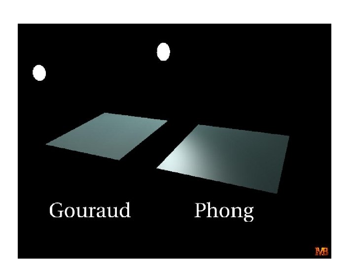
Smooth Shading • Need to have per-vertex normals • Gouraud Shading – Interpolate color across triangles – Fast, supported by most of the graphics accelerator cards • Phong Shading – Interpolate normals across triangles – More accurate, but slow. Not widely supported by hardware
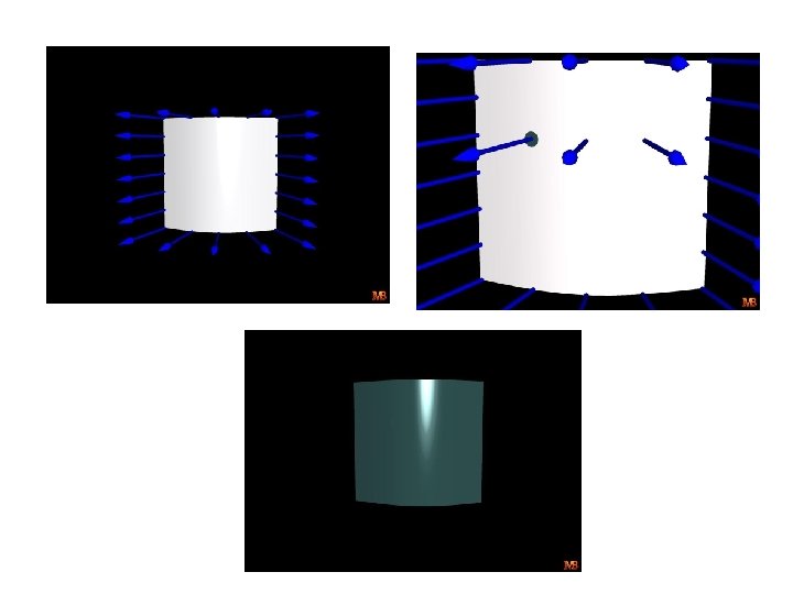
Gouraud Shading • Normals are computed at the polygon vertices • If we only have per-face normals, the normal at each vertex is the average of the normals of its adjacent faces • Intensity interpolation: linearly interpolate the pixel intensity (color) across a polygon surface
Linear Interpolation • Calculate the value of a point based on the distances to the point’s two neighbor points • If v 1 and v 2 are known, then x = b/(a+b) * v 1 + a/(a+b) * v 2
Linear Interpolation in a Triangle • To determine the intensity (color) of point P in the triangle, • we will do: • determine the intensity of 4 by linearly interpolating between 1 and 2 • determine the intensity of 5 by linearly interpolating between 2 and 3 • determine the intensity of P by linear interpolating between 4 and 5
Mach Band ?
Image
Phong Shading Model § Gouraud shading does not properly handle specular highlights, specially when the n parameter is large (small highlight). §Reason: colors are interpolated. §Solution: (Phong Shading Model) § 1. Compute averaged normal at vertices. § 2. Interpolate normals along edges and scan-lines. (component by component) § 3. Compute per-pixel illumination.