Component Identification Digital Introduction to Logic Gates and
- Slides: 25
Component Identification: Digital Introduction to Logic Gates and Integrated Circuits Digital Electronics © 2014 Project Lead The Way, Inc.
This presentation will. . • Introduce transistors, logic gates, integrated circuits (ICs), and explain the relationship of each. • Describe the structure of a truth table and how to “count in binary”. (possible input combinations) • Present an overview of : • Transistor-Transistor Logic – TTL • Complementary Metal Oxide Semiconductor - CMOS • Define the scale of integration and package styles. • Describe the TTL logic gate numbering system. • Introduce Manufacturer Datasheets. 2
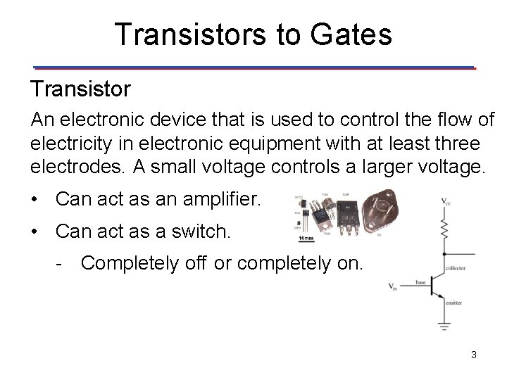
Transistors to Gates Transistor An electronic device that is used to control the flow of electricity in electronic equipment with at least three electrodes. A small voltage controls a larger voltage. • Can act as an amplifier. • Can act as a switch. - Completely off or completely on. 3
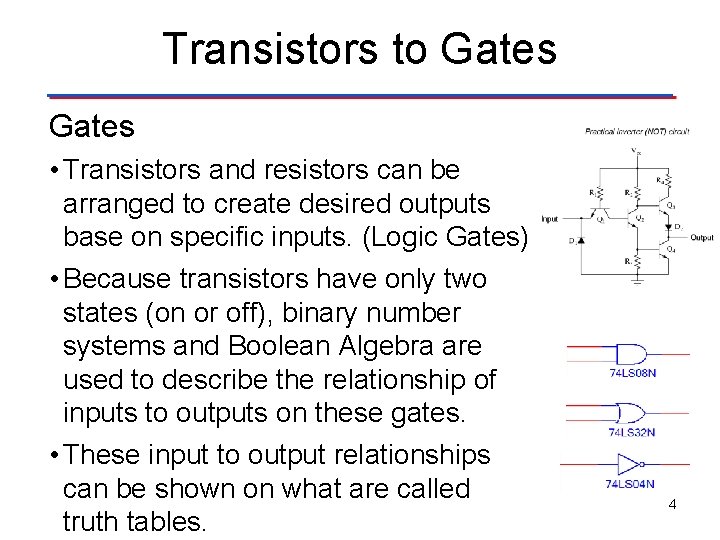
Transistors to Gates • Transistors and resistors can be arranged to create desired outputs base on specific inputs. (Logic Gates) • Because transistors have only two states (on or off), binary number systems and Boolean Algebra are used to describe the relationship of inputs to outputs on these gates. • These input to output relationships can be shown on what are called truth tables. 4
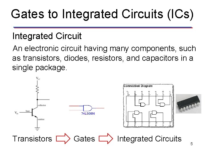
Gates to Integrated Circuits (ICs) Integrated Circuit An electronic circuit having many components, such as transistors, diodes, resistors, and capacitors in a single package. Transistors Gates Integrated Circuits 5
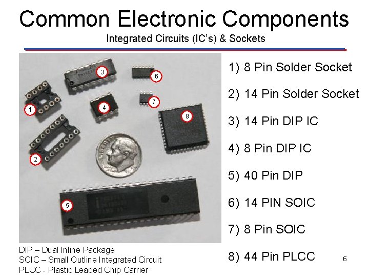
Common Electronic Components Integrated Circuits (IC’s) & Sockets 3 4 1 1) 8 Pin Solder Socket 6 2) 14 Pin Solder Socket 7 8 3) 14 Pin DIP IC 4) 8 Pin DIP IC 2 5) 40 Pin DIP 5 6) 14 PIN SOIC 7) 8 Pin SOIC DIP – Dual Inline Package SOIC – Small Outline Integrated Circuit PLCC - Plastic Leaded Chip Carrier 8) 44 Pin PLCC 6
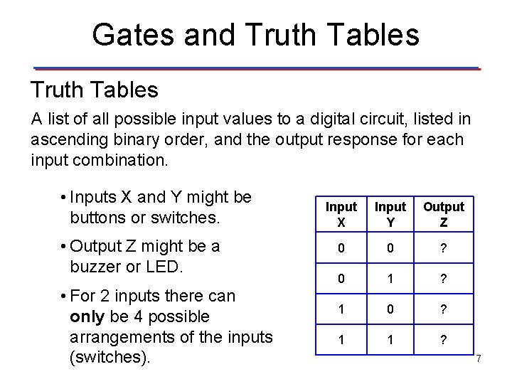
Gates and Truth Tables A list of all possible input values to a digital circuit, listed in ascending binary order, and the output response for each input combination. • Inputs X and Y might be buttons or switches. • Output Z might be a buzzer or LED. • For 2 inputs there can only be 4 possible arrangements of the inputs (switches). Input X Input Y Output Z 0 0 ? 0 1 ? 1 0 ? 1 1 ? 7
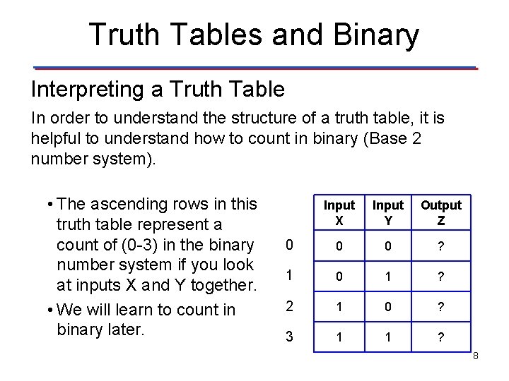
Truth Tables and Binary Interpreting a Truth Table In order to understand the structure of a truth table, it is helpful to understand how to count in binary (Base 2 number system). • The ascending rows in this truth table represent a count of (0 -3) in the binary number system if you look at inputs X and Y together. • We will learn to count in binary later. Input X Input Y Output Z 0 0 0 ? 1 0 1 ? 2 1 0 ? 3 1 1 ? 8
Truth Tables and Binary • For this activity in is only important to know that the truth table is showing is all possible output responses for each input combination. (2 inputs = 4 possible outputs) • All possible input values to a digital circuit are listed in ascending binary order on the truth table. • We will explore the binary number system in detail and how to create your own truth tables in future activities. 9
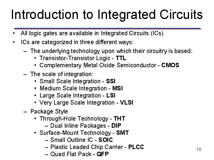
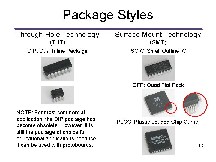
Introduction to Integrated Circuits • All logic gates are available in Integrated Circuits (ICs) • ICs are categorized in three different ways: – The underlying technology upon which their circuitry is based: • Transistor-Transistor Logic - TTL • Complementary Metal Oxide Semiconductor - CMOS – The scale of integration: • Small Scale Integration - SSI • Medium Scale Integration - MSI • Large Scale Integration - LSI • Very Large Scale Integration - VLSI – Package Style • Through-Hole Technology - THT – Dual Inline Packages - DIP • Surface-Mount Technology - SMT – Small Outline IC - SOIC – Plastic Leaded Chip Carrier - PLCC – Quad Flat Pack - QFP 10
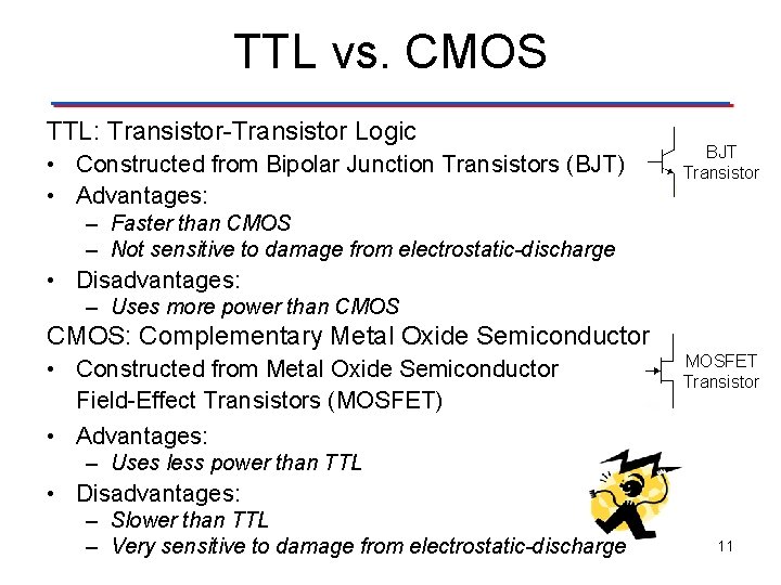
TTL vs. CMOS TTL: Transistor-Transistor Logic • Constructed from Bipolar Junction Transistors (BJT) • Advantages: BJT Transistor – Faster than CMOS – Not sensitive to damage from electrostatic-discharge • Disadvantages: – Uses more power than CMOS: Complementary Metal Oxide Semiconductor • Constructed from Metal Oxide Semiconductor Field-Effect Transistors (MOSFET) • Advantages: MOSFET Transistor – Uses less power than TTL • Disadvantages: – Slower than TTL – Very sensitive to damage from electrostatic-discharge 11
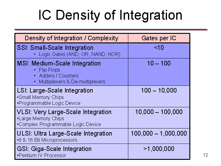
IC Density of Integration / Complexity SSI: Small-Scale Integration Gates per IC <10 • Logic Gates (AND, OR, NAND, NOR) MSI: Medium-Scale Integration 10 – 100 • Flip Flops • Adders / Counters • Multiplexers & De-multiplexers LSI: Large-Scale Integration 100 – 10, 000 • Small Memory Chips • Programmable Logic Device VLSI: Very Large-Scale Integration 10, 000 – 100, 000 • Large Memory Chips • Complex Programmable Logic Device ULSI: Ultra Large-Scale Integration 100, 000 – 1, 000 • 8 & 16 Bit Microprocessors GSI: Giga-Scale Integration • Pentium IV Processor >1, 000 12
Package Styles Through-Hole Technology Surface Mount Technology (THT) (SMT) DIP: Dual Inline Package SOIC: Small Outline IC QFP: Quad Flat Pack NOTE: For most commercial application, the DIP package has become obsolete. However, it is still the package of choice for educational applications because it can be used with protoboards. PLCC: Plastic Leaded Chip Carrier 13
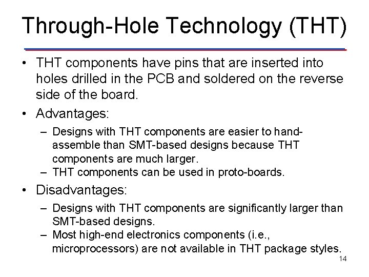
Through-Hole Technology (THT) • THT components have pins that are inserted into holes drilled in the PCB and soldered on the reverse side of the board. • Advantages: – Designs with THT components are easier to handassemble than SMT-based designs because THT components are much larger. – THT components can be used in proto-boards. • Disadvantages: – Designs with THT components are significantly larger than SMT-based designs. – Most high-end electronics components (i. e. , microprocessors) are not available in THT package styles. 14
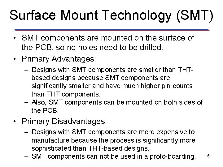
Surface Mount Technology (SMT) • SMT components are mounted on the surface of the PCB, so no holes need to be drilled. • Primary Advantages: – Designs with SMT components are smaller than THTbased designs because SMT components are significantly smaller and have much higher pin counts than THT components. – Also, SMT components can be mounted on both sides of the PCB. • Primary Disadvantages: – Designs with SMT components are more expensive to manufacture because the process is significantly more sophisticated than THT-based designs. – SMT components can not be used in a proto-boarding. 15
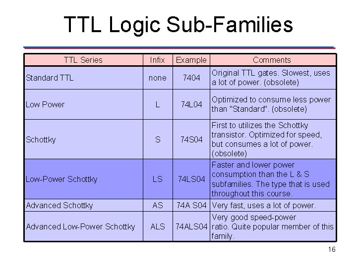
TTL Logic Sub-Families TTL Series Standard TTL Low Power Infix Example Comments none 7404 Original TTL gates. Slowest, uses a lot of power. (obsolete) L 74 L 04 Optimized to consume less power than "Standard". (obsolete) First to utilizes the Schottky transistor. Optimized for speed, 74 S 04 but consumes a lot of power. (obsolete) Faster and lower power consumption than the L & S 74 LS 04 subfamilies. The type that is used throughout this course. Schottky S Low-Power Schottky LS Advanced Schottky AS 74 A S 04 Very fast, uses a lot of power. ALS Very good speed-power 74 ALS 04 ratio. Quite popular member of this family. Advanced Low-Power Schottky 16
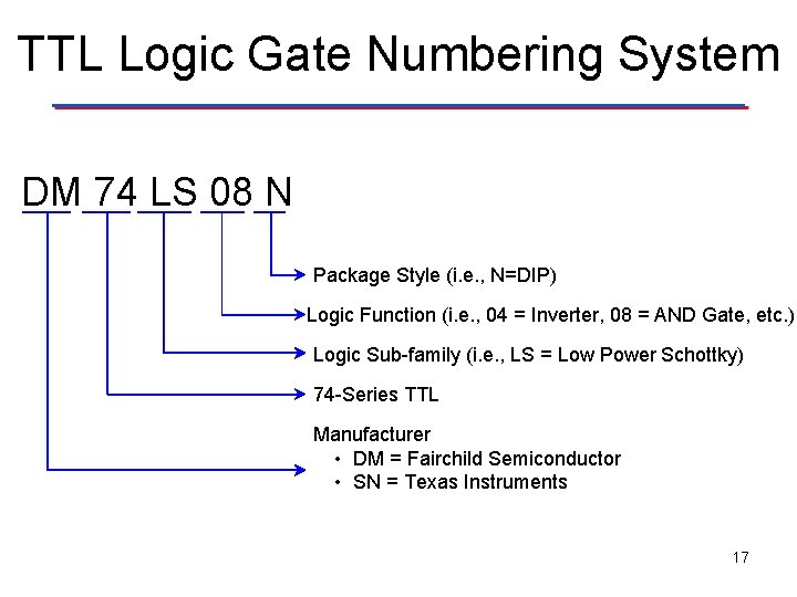
TTL Logic Gate Numbering System DM 74 LS 08 N Package Style (i. e. , N=DIP) Logic Function (i. e. , 04 = Inverter, 08 = AND Gate, etc. ) Logic Sub-family (i. e. , LS = Low Power Schottky) 74 -Series TTL Manufacturer • DM = Fairchild Semiconductor • SN = Texas Instruments 17
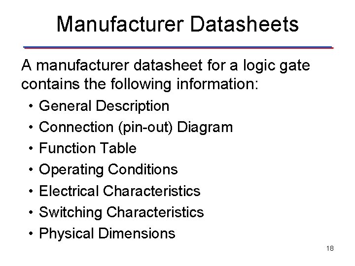
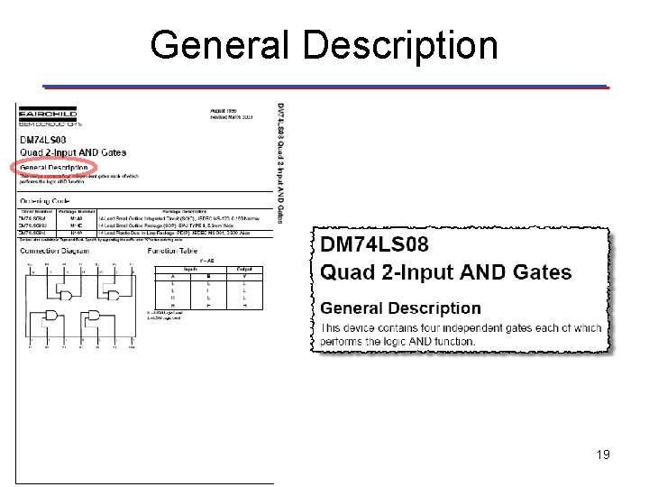
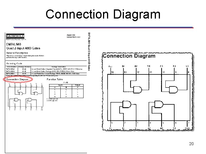
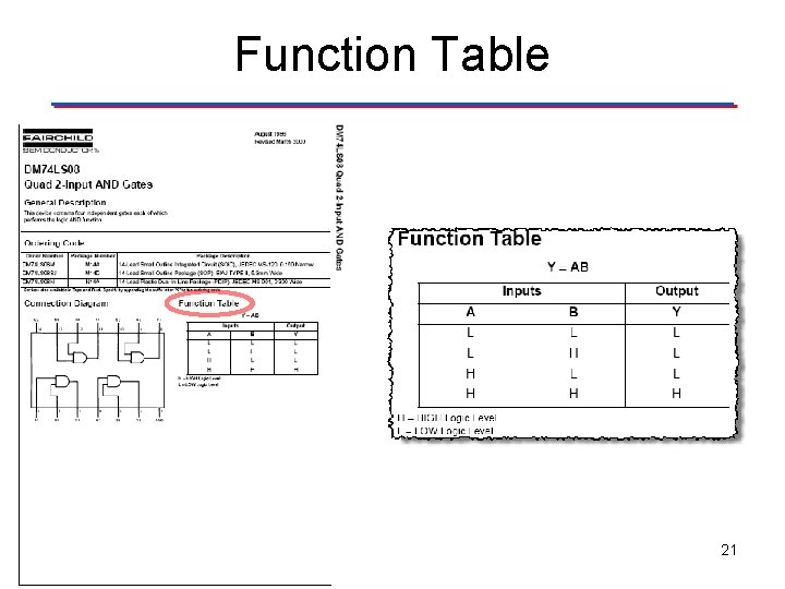
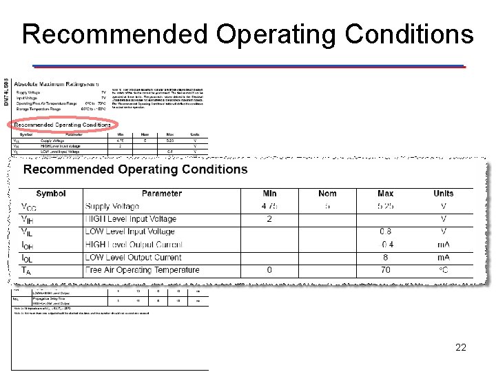
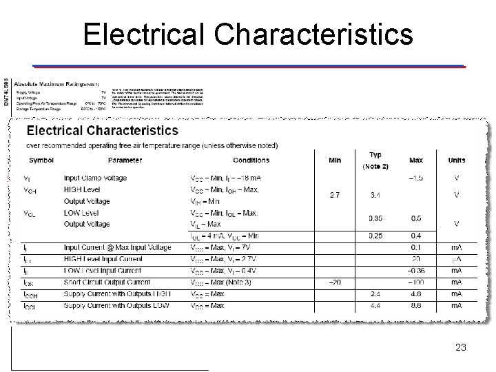
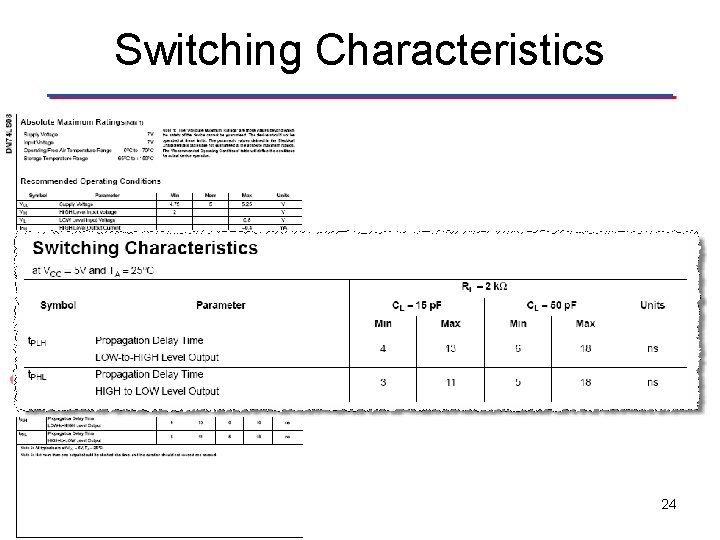
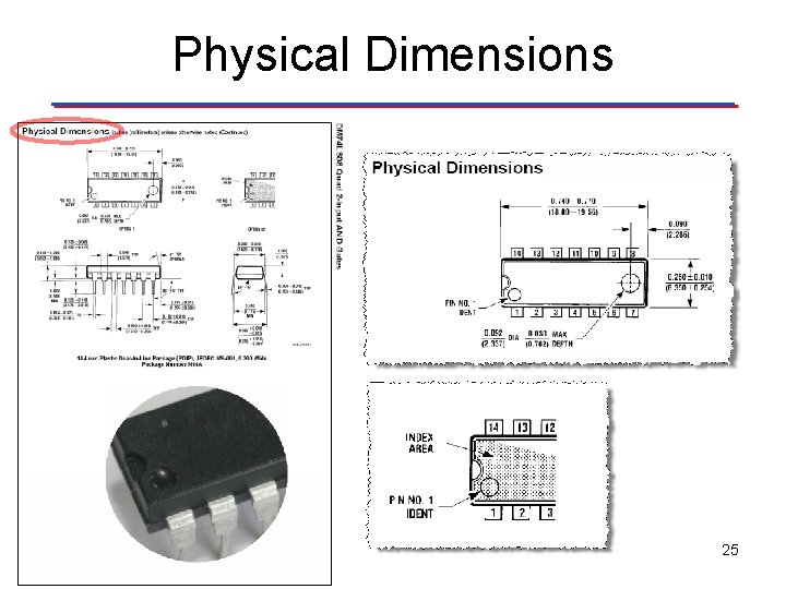
Manufacturer Datasheets A manufacturer datasheet for a logic gate contains the following information: • General Description • Connection (pin-out) Diagram • Function Table • Operating Conditions • Electrical Characteristics • Switching Characteristics • Physical Dimensions 18
General Description 19
Connection Diagram 20
Function Table 21
Recommended Operating Conditions 22
Electrical Characteristics 23
Switching Characteristics 24
Physical Dimensions 25