Digital Logic Design Chapter 2 Digital Systems and


10 2 -")
’s Complement The (r – 1)’s comp. of a")
10 2 -")


10 , (-12)10 in signmagnitude, 1’s and 2’s complement?")
 with r’s comp.")

10 using r’s comp? Sol :")

’s complement The procedure for subtracting two numbers (M–N) with (r-1)’s comp.")

16 -( 4 8")

 8421 Excess-3 8 4 -2 -1")
10 to Binary , BCD code? Sol: -")


")


- Slides: 54
Digital Logic Design Chapter 2 Digital Systems and Binary Numbers Al-Mustansiriyah University College of Science Computer Department Dr. Ghassan M. Al-Saddi
Outline of Chapter 2 © 1. 1 Counting in Number Systems © 1. 2 The Complement © 1. 3 Binary Codes © 1. 4 Binary Logic and Logic Gates © 1. 5 Boolean Function Algebra
Counting in Number Systems The counting in any system is done by starting with the first digit in the system ( 0 ) until the maximum digit of the system is reached and then the counting is continue using 2 digits and so on. Ex: Write first 17 digits in base 8? Sol: ( 0, 1, 2, 3, 4, 5, 6, 7, 10, 11, 12, 13, 14, 15, 16, 17, 20 )
Counting in Number Systems Ex: Write first 30 digits in Hexadecimal system? Sol: ( 0, 1, 2, 3, 4, 5, 6, 7, 8, 9, A, B, C, D, E, F, 10, 11, 12, 13, 14, 15, 16, 17, 18, 19, 1 A, 1 B, 1 C, 1 D) Ex: Write 10 digits in base 8 starting with decimal 5? Sol: ( 5, 6, 7, 10. 11, 12, 13, 14, 15, 16)
The Complements are used in digital computer for simplifying the subtraction operation and for logical manipulations. There are two types of complements for each base R system: 1– The r’s complement. 2 – The ( r – 1 )’s complement.
The r’s Complement The r’s complement of number is obtained by subtracting the first nonzero least significant digit from the base of the system, and subtracting all other higher digits from (base-1).
Example 1 - The 10’s comp. of ( 5 2 0 )10 2 - The 10’s comp. of ( 3 2 6 7 )10 3 - The 10’s comp. of ( 2 5. 6 3 9 )10 4 - The 2’s comp. of ( 1 0 1 1 0 0 )2 5 - The 11’s comp. of ( 8 7 6 5)11 6 - The 16’s comp. of ( A 0 9 0 )16 (47480) (6733) (74. 361) (010100) (2346) (5 F 70)
The ( r - 1 )’s Complement The (r – 1)’s comp. of a number is obtained by subtracting every digit from the ( base – 1 ).
Examples 1 - The 10’s comp. of ( 5 2 0 )10 2 - The 10’s comp. of ( 3 2 6 7 )10 3 - The 10’s comp. of ( 2 5. 6 3 9 )10 4 - The 2’s comp. of ( 1 0 1 1 0 0 )2 5 - The 11’s comp. of ( 8 7 6 5)11 6 - The 16’s comp. of ( A 0 9 0 )16 (47479) (6732) (74. 360) (010011) (2345) (5 F 6 F)
As a result in Binary system the 1’s comp. is obtained by change each 1 to 0 and the 0 to 1, and the 2’s comp. is obtained by adding 1 to the 1’s comp. Ex: Find the 1’s and 2’s comp. of ( 1 0 1 1 0 0 )2 ?
The Negative Numbers There are three types or methods to represent the negative numbers in a computer: 1 - Sign–and–Magnitude (signmagnitude). 2 - 1’s complement. 3 - 2’s complement.
The Negative Numbers Ex Represent (+12)10 , (-12)10 in signmagnitude, 1’s and 2’s complement? Sol : signmagnitude 1’s comp. 2’s comp +12 0 1 1 0 0 -12 1 1 1 0 0 1 0 0 1 1 1 0 1 0 0 for sign
Subtraction with r’s complement The procedure for subtracting two numbers (M–N) with r’s comp. is done as follow: 1 – Find the r’s comp. of N. 2 – Add M to the result of step 1. 3– Inspect the result obtained in step 2 for an end carry: a – If an end carry occurs, discard it. b – If an end carry does not occurs, take the r’s comp. of the number obtained in step 2 and place negative sign in front of it.
Subtraction with r’s complement Ex Subtract ( 7 2 5 3 2 - 3 2 5 0 ) 10 using 10’s comp. ? Sol: M = 7 2 5 3 2 , N = 0 3 2 5 0 1 – the 10’s comp. of N is ( 9 6 7 5 0 ) 2 - 7 2 5 3 2 + 9 6 7 5 0 -------- 1 6 9 2 8 2 3 – The result is ( 6 9 2 8 2 ) 10
Subtraction with r’s complement Ex Subtract (3250 - 72532)10 using r’s comp? Sol : M=03250 , N=72532 1 - The l 0’s comp. of N is ( 2 7 4 6 8 ) 2 - 0 3 2 5 0 + 2 7 4 6 8 ------- 3 0 7 1 8 there is no carry 3 - The l 0’s comp. of ( 3 0 7 1 8 ) is ( 6 9 2 8 2 ) The result is -( 6 9 2 8 2 )10
Subtraction with r’s complement Ex Subtract ( 1 0 0 0 1 0 0 )2 -( 1 01 0 0 ) 2 using 2’s comp. ? Sol M=1 0 0 0 1 0 0 , N = 1 0 1 0 0 1 - The 2’s comp of N is ( 0 1 1 0 0 ) 21 0 0 0 1 0 0 + 0 1 1 0 0 --------- 1 1 1 0 0 there is no carry 3 - The 2’s comp. of ( 1 1 1 0 0 ) is ( 0 0 1 0 0 ) The result ( 1 0 0 )
Subtraction with (r-1)’s complement The procedure for subtracting two numbers (M–N) with (r-1)’s comp. is done as follow: 1 – Find the (r-1)’s comp. of N. 2 – Add M to the result of step 1. 3– Inspect the result obtained in step 2 for an end carry: a – If an end carry occurs, add 1 to the least significant digit. b – If an end carry does not occurs, take the (r-1)’s comp. of the number obtained in step 2 and place negative sign in front of it.
Ex Find 83 -27 using 1’s comp? Sol M = 83 = ( 1 0 0 1 1 )2 , N = 27 = ( 0 0 1 1 )2 1 - The 1’s comp. of N is ( 1 1 0 0 ) 2 - 1 0 0 1 1 + 1 1 0 0 ----------- 1 0 1 1 1 3 - 0 1 1 1 + 1 --------- 1 1 1 0 0 0 the result is ( 1 1 1 0 0 0 )
Ex Perform the operation ( A B C E F )16 -( 4 8 F 9 D )16 using (r– 1)’s comp. ? Sol: M = (A B C E F) , N = (4 8 F 9 D) 1 - The 15’s comp. of N is ( B 7 0 6 2 ) 2 - A B C E F + B 7 0 6 2 ----------- 1 6 2 D 5 1 3 - 6 2 D 5 1 + 1 ---------- 6 2 D 5 2 the result is ( 6 2 D 5 2 )16
Binary Codes Binary codes for decimal digit require a minimum of four bits. Numerous different code can be obtained by arranging four or more bits in many distinct possible combinations. A few possibilities are shown in the table: -
Binary Codes Decimal Digit ( B C D) 8421 Excess-3 8 4 -2 -1 0 1 2 3 4 5 6 7 8 9 0 0 0 0 1 1 0 1 0 0 0 1 0 1 0 1 1 0 0 1 1 1 1 0 0 0 1 1 0 1 0 1 1 0 0 0 0 1 1 1 0 0 1 0 1 0 1 1 1 0 1 0 0 1 1 0 0 0 1 1 Ø In BCD code ( Binary Coded Decimal ) each decimal number is represented in 4 bits. Ø In Excess – 3 Code each decimal number is represented by adding 3 to each number in BCD code.
Binary Codes Ex Convert ( 13 )10 to Binary , BCD code? Sol: - ( 13 )10 = ( 1 1 0 1 )2 ( 13 )10 = ( 0 0 0 1 1 ) BCD Ex Decode the following BCD numbers? 1 – ( 1 0 0 0 1 0 1 ) BCD 2 – ( 1 1 0. 0 1 1 0 1 )BCD Sol : 1 – ( 0 1 0 0 0 1 0 1 ) BCD = ( 4 7 8 9 5 )10
Binary Codes Ex Encode the following numbers into BCD code? 1 – ( 1 1 1 0 0 1 1 ) 2 – ( 7 6 4 8 )10 Sol : 1 – 1 1 1 0 0 1 1 = 1 x 20 + 1 x 21 + 0 x 22 + 0 x 23 + 1 x 24 + 1 x 25 + 1 x 26 = 1 + 2 + 0 + 16 + 32 + 64 = ( 115 )10 = ( 0001 0101 ) BCD Ex What are the Ex-3 of the following numbers? 1 – ( 3 6 5 ) 10 2 – ( 1 1 0 1 0 ) 2 Sol 3 6 5 +3 +3 +3 --------- 6 9 8
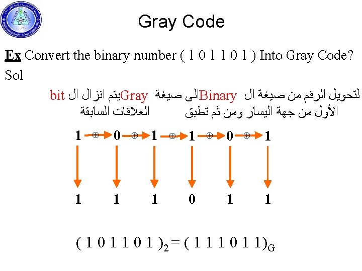
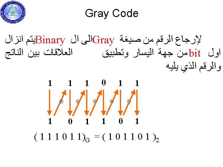
Gray Code To convert the number from binary to Gray code the relations must be known. 1 ⊕ 1 = 0 1 ⊕ 0 = 1 0 ⊕ 1 = 1 0 ⊕ 0 = 0
ASCII Character Code The standard binary code for the alphanumeric characters is called ASCII (American Standard Code for Information Interchange). It uses 7 bits to code 128 characters, as shown in the table. The seven bits of the code are designed by A 0 through A 6, with A 6 being the most significant bit (MSB). For example, the letter A is represented n ASCII as ( 1000001 ). The ASCII code contains 94 characters that can print and 34 nonprinting used in control functions. The printing characters consist of 26 uppercase letters, the 26 lowercase letters, 10 numerals, and 32 special printable character such as %, @ and $.
ASCII Character Code
ASCII Character Ex What are the character corresponding to the ASCII code? (10000111110011011010000101011 01001011010010) ASCII Sol (1000011 1001101 1010000 101010100 1000101 1010010) ASCII = COMPUTER
Binary Logic and Logic Gates Binary logic is used to describe, in mathematical way, the manipulation and processing of binary information. It is suited for the analysis and design of digital system. The logic circuits (gates) establish the logical manipulation. The logic gates are: -
Logic Gates 1– Buffer Gate Q = A Logic Symbol Logic Equation Truth Table 2– NOT Gate Q = Ā Logic Symbol Logic Equation Truth Table
Logic Gates 3– OR Gate Q = A + B Logic Symbol Logic Equation Truth Table 4– AND Gate Q = A. B Logic Symbol Logic Equation Truth Table
Logic Gates AND OR
Logic Gates 5– NOR Gate Logic Symbol Logic Equation Truth Table 6– NAND Gate Logic Symbol Logic Equation Truth Table
Logic Gates ©
Boolean Algebra
Boolean Algebra
Complementing Functions
Boolean Function Evaluation A binary variable can take the value of 0 or 1. A Boolean function is an expression formed with binary variable, the two binary operators OR and AND, the NOT operator, parentheses and equal sign. For a given value of the variables, the function can be either 0 or 1. Any Boolean function can be represented in a truth table. The number of rows in the table is n 2, where n is the number of binary variables in the function. The binary numbers is then counting from 0 to n 2 -1. The Boolean function may be transformed to logic diagram composed of AND, OR and NOT gates.
Boolean Function Input X Y Z F 1 0 0 1 1 0 0 0 1 1 0 0 1 1 0 1 0 1 output F 2
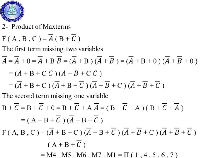
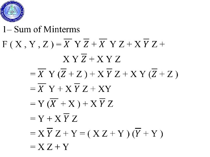
Canonical and Standard Forms Minterms and Maxterms: Any Boolean function can be expressed in a canonical form, canonical form include: 1 - Sum of Minterms (SOM) 2 - Product of Maxterms ( POM ) In Minterms each variable being primed if the corresponding bit of the binary number is 0 and unprimed if a 1. In Maxterms each variable being unprimed if the corresponding bit of the binary number is 0 and primed if a 1.
Minterms & Maxterms X Y Z Designation Maxterms Designation 0 0 0 m 0 X+Y+Z M 0 0 0 1 m 1 M 1 0 m 2 M 2 0 1 1 m 3 M 3 1 0 0 m 4 M 4 1 0 1 m 5 M 5 1 1 0 m 6 M 6 m 7 M 7 1 1 1 Minterms X Y Z The Sum of Minterms of the function is expressed by the ORing to the minterms when the output is 1 ( F = 1 ). The Product of Maxterms of the function is expressed by ANDing to the maxterms when the output is 0 ( F = 0 ).
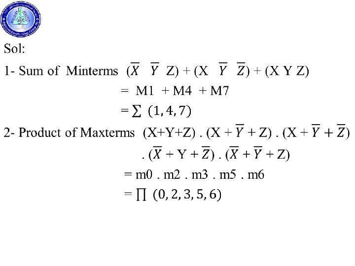
Ex Find the Sum of Minterms and Product of Maxterms of F: X Y Z F 0 0 0 1 1 0 1 0 1 1 0 0 1 1
Ex Express each of the following functions in Canonical Forms. X Y Z F 1 F 2 0 0 0 0 1 1 1 0 1 0 0 1 1 1 0 0 0 1 1 1
Ex express the function F in Sum of Minterms and Product of Maxterms and simplify it X Y Z F 0 0 0 1 0 1 1 0 0 0 1 1 1 1 0 1 1 1
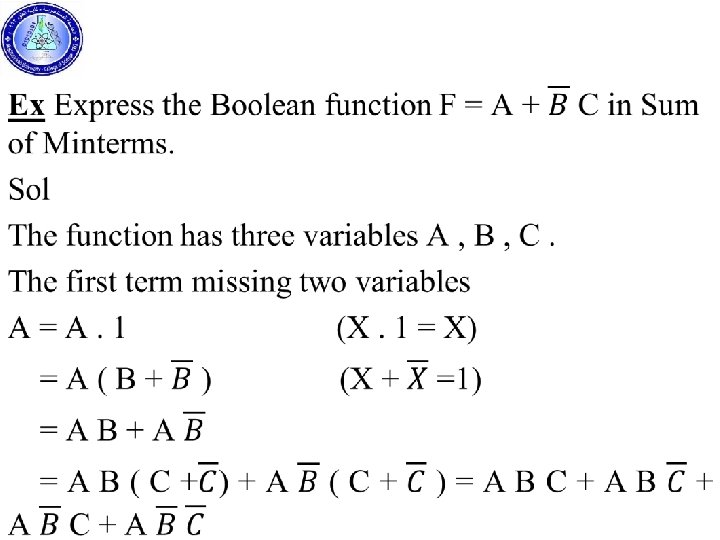
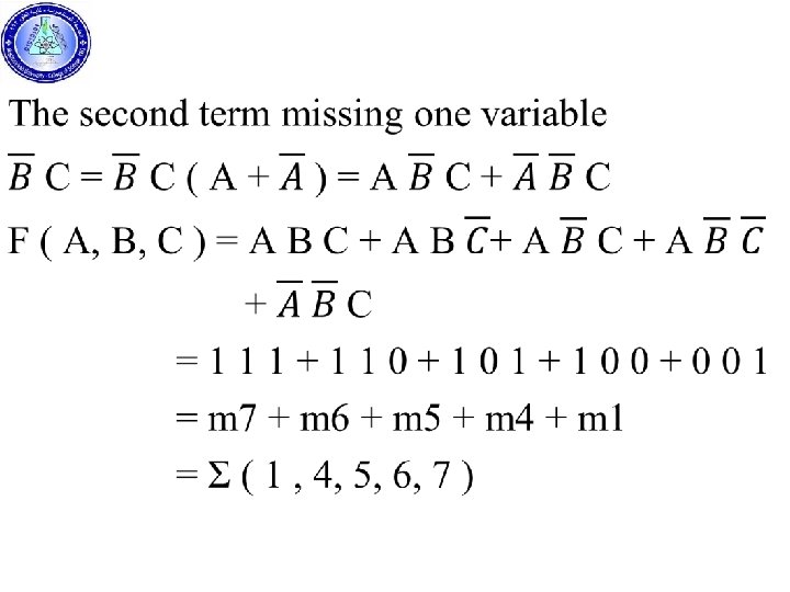
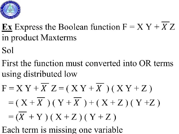
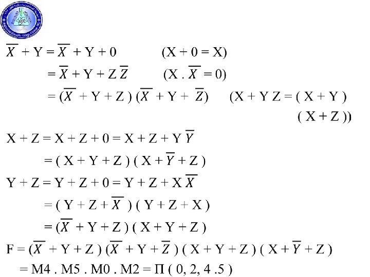
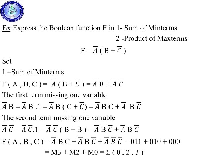
Standard Forms