COMET staging plan COMET JPARC E 21 Pion


4 μ νμ mixing νe e W")
 • BR = 10 -14")
![Principle of Measurement SINDRUM II BR[μ- + Au →e- + Au] < 7 ×](https://slidetodoc.com/presentation_image_h2/5f8cd26651c29afcca02c3b87f214bcc/image-6.jpg "Principle of Measurement SINDRUM II BR[μ- + Au →e- + Au] < 7 ×")


 • • • Measure almost all particles")

 SX beam 0. 00001 k. W -")


 and then MECO (the US) •")
→(A, Z-1)* →γ+(A, Z-1) γ→e+e. Prompt timing Other")


 R=9. 7Ω")


 & g 4 beamline (simulation)")


- Slides: 43
COMET staging plan 齊藤 直人・三原 智
COMET J-PARC E 21 Pion collection Proton Beam Utilize J-PARC Hi- Intensity proton beam 8 Ge. V, 7μA Muon transport Search for LFV process, μ-e conversion with a sensitivity of 10 -16 Innovative apparatus Pion collection Muon Transport Electron Spectrometer Pion production target Muon stopping target
μ−電子転換とは? 1 s state in a muonic atom nucleus Neutrino-less muon nuclear capture (=μ-e conversion) − , (A Z) e μ + + (A, Z) − − μ lepton flavours changes by one unit Muon Decay In Orbit − − μ e νν nuclear muon capture μ + ( A, Z) ν μ + ( A, Z − 1) − • Eμe ~ mμ-Bμ – Bμ: binding energy of the 1 s muonic atom − − e ( N N) Γ μ − − B( μ N e N) = ' − Γ(μ N ν N )
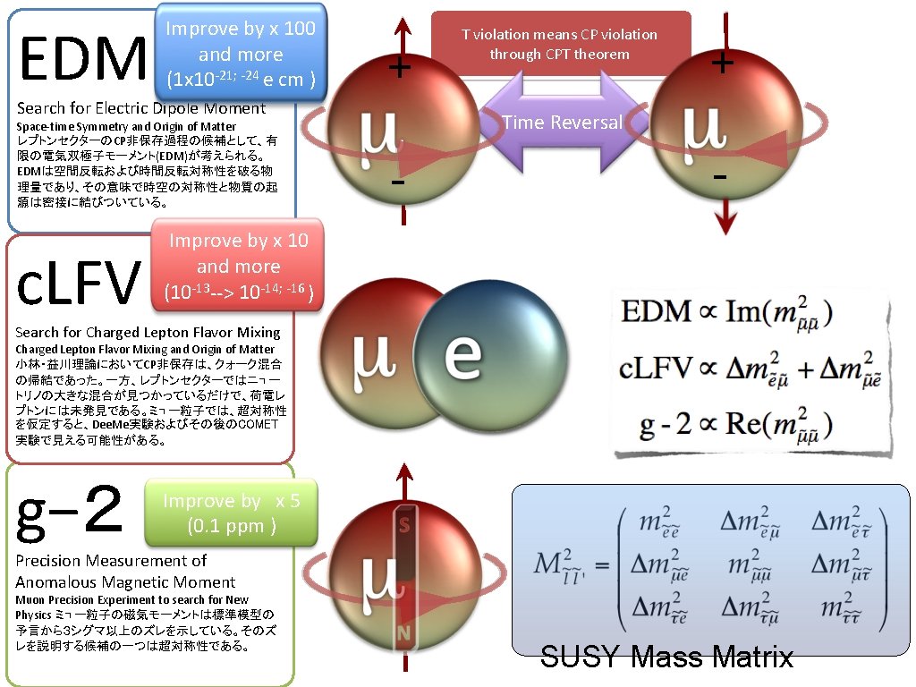
Lepton-Flavor Violation in Charged Lepton Sector ∝(mν/m. W)4 μ νμ mixing νe e W Very Small (10 -54) large top-Yukawa coupling ~ μ mixing μ ~B ~ e e Sensitive to new Physics beyond the Standard Model
Theoretical Models • • SUSY-GUT, SUSY-seesaw (Gauge Mediated process) • BR = 10 -14 = BR(μ→eγ) × O(α) • τ→lγ SUSY-seesaw (Higgs Mediated process) • BR = 10 -12~10 -15 • τ→lη MEG 2011 2. 4 x 10 -12 • Doubly Charged Higgs Boson (LRS etc. ) • Logarithmic enhancement in a loop diagram for μ -N → e-N, not for μ→e γ • • M. Raidal and A. Santamaria, PLB 421 (1998) 250 and many others Andre de Gouvea, W. Molzon, Project-X WS (2008)
Principle of Measurement SINDRUM II BR[μ- + Au →e- + Au] < 7 × 10 -13 • Process : μ- +(A, Z) →e- +(A, Z) • A single mono-energetic electron • Eμe(Al) ~ mμ-Bμ : 105 Me. V • Delayed:~1μS • No accidental backgrounds • Physics backgrounds • Muon Decay in Orbit (DIO) • Ee > 102. 5 Me. V (BR: 10 -14) • Ee > 103. 5 Me. V (BR: 10 -16) • Beam Pion Capture • π-+(A, Z) → (A, Z-1)* → γ+(A, Z-1) γ → e + e- Rext= number of proton between pulses number of proton in a pulse 1 -2μs
温故知新 Use pulse beam instead of DC beam Blind to prompt background using timing information Reduce pion background arriving in a delayed timing Good beam extinction factor Sensitive only high-momentum electrons emitted in a delayed timing
COMET Phase I
Eo. I
COMET Phase-I Lo. I • Beam background Study • μ-e conversion search
Purpose of the study • • • Verify pion collection using a solenoid magnet surrounding a production target at 8 Ge. V Direct measurement of residual dose at the COMET beam line with lower beam power ( < 1 k. W) Identify particles contained in the beam and measure their phase space to better understand possible background in COMET • • No available data of particle production backward at 8 Ge. V Antiproton and neutron yield Current COMET BG is estimated by extrapolating existing data by 4 orders of magnitude! Cosmic-ray associated and room background in the hall as well
Beam Background Study Plan
Setup Co. COMET (or COMETino or COMETChen) • • • Measure almost all particles Same detector technology used in COMET • • • SC spectrometer solenoid Straw tube transverse tracker Crystal calorimeter Particle ID with d. E/d. X and E/p • • anti-p with event shape γ direction
Particles and Yield μ • Beam dispersion • • + μ Collimator to reject highp particles Positive/negative particles contained in the beam with wide momentum range w/o collimator
Beam Requirement • • Continuous (not pulsed) SX beam 0. 00001 k. W - 0. 1 k. W beam power for approximately 3 cycles (approx. 3 months) • precise estimation in future 8 Ge. V beam extraction is necessary for beam study • conditioning can be done at 30 Ge. V as long as the beam power is small enough not to produce significant residual dose around the target Requesting to the accelerator group for 8 Ge. V beam extraction study before 2016
Sensitivity and BG • • 8 Ge. V, 3. 2 k. W proton beam • 2. 5 x 10¹² proton/sec 12 days (106 sec) running time Single event sensitivity • B(μ-+Al→e-+Al) = 3. 1 x 10 -15 one signal event assuming B(μ-e)=3 x 10 -15 0. 05 BG events Upper limit at 90% C. L. • B(μ-+Al→e-+Al) < 7. 2 x 10 -15 Selection Value Comments Geometrical Acc 0. 53 tracking eff. included momentum 0. 50 pe>101. 9 Me. V/c Timing 0. 39 same as COMET Trigger and DAQ 0. 9 same as COMET Total 0. 09 supposing beam extinction factor of 10 -9
Facilities • • • Building construction in 2013 -2015 High-p beam line installation in 2015 followed by COMET beam line installation in 2016 Detector installation can be started when the building construction completes
Covered by Exp. Group Budget Request KEK internal Schedule 2012 -2013 design 2013 -2015 construction 2015 -2016 installation 2016 Beam study 2017 Engineering/physics run 4 10 Exp. area ready starting installation 6 installation complete
Cost Estimate • • 1 Oku JPY = 1 M € Based on • • KEK facility department cost estimate Toshiba design Building 9. 5 Oku Budget request 20 Oku JPY includes building, beam line, magnet (up to 1 st 90 o bend) Expect support from J-PARC project budget Magnet 9 Oku Detector construction by the experiment group by external funding Beam Line 6. 3 Oku Detector 11. 5 Oku Budget request 20 Oku experiment group 11. 8 Oku J-PARC project budget 4. 5 Oku
COMET Phase-I Proto-collaboration • 107 collaborators • 25 institutes • 11 countries
g-2, EDM and c. LFV n. Large g-2 Large c. LFV Large EDM J. Hisano, Nagai, Paradisi 0. 5 0. 4 0. 3 BR(μ→e; Ti)× 1013 G. Isidori, F. Mescia, P. Paradisi, and D. Temes, PRD 75 (2007) 115019 0. 2 Current limit by MEG 2. 4 x 10 -12 13
The SINDRUM II Experiment at PSI Published Results SINDRUM-II used a continuous muon beam from the PSI cyclotron. To eliminate beam related background from a beam, a beam veto counter was placed.
The MELC and MECO Proposals • MELC (Russia) and then MECO (the US) • To eliminate beam related background, beam pulsing was adopted (with delayed measurement) • To increase a number of muons available, pion capture with a high solenoidal field was adopted • For momentum selection, curved solenoid was adopted Cancelled in 2005 mu 2 e @ Fermilab Vladimir Lobashev 1934 -2011 CERN Courier Vol 51, No 8
Beam Extinction Factor COMET Background π-+(A, Z)→(A, Z-1)* →γ+(A, Z-1) γ→e+e. Prompt timing Other sources μ- decay-in-flight, e- scattering, neutron streaming Nbg = NP x Rext x Yπ /P x Aπ x Pγ x A NP : total # of protons (~1021) Rext : Extinction Ratio (10 -9) Yπ /P : π yield per proton (0. 015) Aπ : π acceptance (1. 5 x 10 -6) Pγ : Probability of γ from π (3. 5 x 10 -5) A : detector acceptance (0. 18) BR=10 -16, Nbg ~ 0. 1 Extinction factor < 10 -9 1 -2μs 1. 3 or 1. 7μs 100 ns 0. 7 second beam spill 1. 5 second accelerator cycle Extraction Acceleration
COMET Final Configuration Pion collection Proton Beam Pion Collection Muon Transport Momentum selection using a curved solenoid Large acceptance Charge separation using a beam blocker Muon transport Collect low momentum (backward) pions Pion production target Muon stopping target Electron Spectrometer Momentum selection Detector in vacuum to suppress multiple scattering effect Electron Spectrometer
COMET Beam Line Proposal of high-p and COMET beam line construction share the upstream branch from A-line; beam stealer for high-p, bending magnet for COMET branch from high-p line no simultaneous usage of two beam lines Switching dipole magnet is enough COMET needs 8 Ge. V, 7μA (56 k. W) beam K. Tanaka Jan/12 PAC Meeting
Eo. I • Beam study for COMET • • • Extinction measurement at the actual COMET setup Beam particles and momentum distribution at the end of the 1 st 90 degree bend μ-e conversion search at intermediate sensitivity: B(μ-+Al→e-+Al)<7. 2 x 10 -15 at 90% C. L.
J-PARC Proton Acceleration for COMET • RCS: h=2 with one empty bucket • MR: h=9 with 6(5) empty buckets • Bunched slow extraction – Slow extraction with RF cavity ON Realization of an empty bucket in RCS by using the chopper in Linac • Simple solution • No need of hardware modification • Heavier heat load in the scraper • Possible leakage of chopped beam in empty buckets
MR Injection for COMET • Preliminary measurement shows 10 -7 extinction factor • • • ① • Most probably caused by chopper inefficiency Particles must remain in empty buckets at beam injection to MR Once accelerated, difficult to remove Remove remaining particles in empty buckets at beam injection to MR Double injection kicking ② Early injection kicking
Impulse Current WF 1 2 3 4 5 6 7 (T=120 msec) R=9. 7Ω (運転開始時) R=9. 4Ω (最適化後) フラットトップ 1. 2μsecで安定 ①Power Supply/Cable ②Impedance mismatch at high frequency region ③Register mismatch 5 6 7 8 1 2 Rise time: 350 nsec (0 -99%) Need to reduce floating capacitance 3 4 5 6 7 8 Sugimoto J-PARC Acc
μ-e conversion search in COMET Phase-I
COMET Phase-I Goal • • • As an intermediate goal of the COMET experiment • gain experience to reach the final goal 7 x 10 -15 sensitivity (90% C. L. upper limit) • better than the current limit by SINDRUM-II (7 x 10¹³) and compatible to MEG sensitivity Involve more collaborators
Proposed Setup • Cylindrical detector • Transverse tracker detector
Cylindrical Detector • • • Collimator of 200 mm diam. at the end of 90 degree bend • • determine a beam size eliminate high-p particles Beam particles not stopped on the target will escape from the detector Optimization of detector configuration pt threshold > 70 Me. V/c m trigger counter (5 mm thick) as a proton absorber 05 0. 8 • • m 1. 5
after collimation before collimation • • Beam Simulation MARS(production) & g 4 beamline (simulation) Tosca (B field) μ- on the target μ- π- stopped # of particles / proton (x 10 -3) 0. 23% stop μ/proton
Expected Performance μ−+N→N’+p+νμ • Detector hit rate • Proton emission after muon capture • • • peak at 70 Me. V/c and extends to > 200 Me. V/c 15% of muon capture (for Si, no data for Al) Trigger counter as a proton absorber DIO ee+e- from high-E γ conversion Momentum resolution Kinetic Energy [Me. V] 530 k. Hz in the 1 st layer of DC (530 k/345=1. 5 k. Hz/ch) for 5. 8 x 10⁹ muon stops Signal Electron 105 Me. V/c no absorber 5 mm absorber 2 Me. V/c 2. 4 Me. V/c
Transverse Tracking Detector • • • Reuse the detector for beam study • • Beam collimator Beam blocker High-p wedges proton degrader • Signal electron momentum spread 200 Me. V/c (FWHM) Geometrical acceptance smaller than the cylindrical detector: 22. 5% and more beam related background • lower sensitivity 80 k. Hz/ch detector hit rate in the 1 st layer expected for 5 x 10⁹ muon stops/sec Momentum resolution expected as good as COMET (1% in sigma) Sensitivity and BG calculation in progress
Detector R&D • • • Muon profile monitor Straw tube tracker Electron calorimeter Calorimeter electronics group Calorimeter simulation group
Summary • • COMET Staging Plan Phase-I • • • Experimental area and beam line construction up to the end of the 1 st 90 degree bend Beam background study with an actual setup • better understanding of background μ-e conversion search with an intermediate sensitivity • • step to the final goal 10 -16 Sensitivity of 7 x 10 -15 (90% C. L. upper limit) foreseen Start running 2016 (if funding starts in 2013) Phase-II • Beam line upgrade/Spectrometer upgrade/50 k. W accelerator power
COMET vs mu 2 e 2012 2013 2014 2015 Phase-I design 2016 2017 2018 2019 2020 2022 Phase-II design Phase-I construction COMET Phase-II construction Beam Physics 10 -16 Physics 10 -14 Construction mu 2 e 2021 CD 2/3 CD 1 CD 3 b a Eng. Run Physics
High-p Suppression • A center of helical trajectory of charged particles in a curved solenoidal field is drifted by – This effect can be used for charge and momentum selection. • This drift can be compensated by an auxiliary field parallel to the drift direction δ p/δ x = 1 Me. V/c/cm
Extinction Measurement Result • Normal beam injection to MR • Integration over 20 minutes • Extinction level at (5. 4± 0. 6)× 10 -7