JPARC CERN collaboration for Slow Extraction JPARC visit

J-PARC / CERN collaboration for Slow Extraction J-PARC visit F. Velotti, M. Tomizawa, R. Muto …and thanks Matt, Verena and Bren for this!

Outline • Introduction ‣ J-PARC Main Ring • J-PARC slow extraction ‣ SX layout ‣ Operational settings ‣ SX Efficiency and spill duty cycle ‣ Spiral step and collimators ‣ Feedbacks and spill qualuty ‣ Dynamic bump ‣ Beam profiles and positon in the TL ‣ Main problems • What can we learn? • Conclusions

400 Me. V LINAC J-PARC Japan Proton Accelerator Research Complex 3 Ge. V RCS n to SK 3 rd O Slow 30 Ge. V Ma in R ing MLF rder Extr Reso actio nan t n Circumference 1567. 5 m Kinetic Energy 30 Ge. V Betatron tune (22. 333, 20. 78) Repetition 5. 52 sec Spill Length ~2 sec Hadron Experimental Facility Bird’s eye photo 3 in January 2016

Hadron Experimental Facility Hadron Hall Switching Yard multi-strangeness K 1. 8 BR hypernuclei area Main Ring L, X T 1 target kaonic nuclei Proton Beam Splitting Point High-p/COM ET beamline KL area K 1. 1 BR area COMET area f E 16 area Origin of Hadron Mass μ e conversion 4
 Small α ( = 0.")
Beam Envelope Large β ( = 40. 04 m) Small α ( = 0. 017 ) Injection Beam BUMP SMS 3 SMS 2 BUMP SMS 1 Focus Q ESS 1 ESS 2 Focus Q Step Size is ~15/20 mm @ J-PARC 5
 Titanium Electrode Circular Beam Extracted Beam Ribbon ESS 1, 2")
Electro Static Septum (ESS) Titanium Electrode Circular Beam Extracted Beam Ribbon ESS 1, 2 Voltage / Gap Deflection Angle 104 k. V / 25 mm - 0. 2 mrad Core Length 1. 5 m Ribbon Thickness 30 μm Ribbon Width 1 mm Ribbon Interval 3 mm # of Ribbons 495 6
 Small α ( = 0.")
Beam Envelope Large β ( = 40. 04 m) Small α ( = 0. 017 ) Injection Beam BUMP SMS 3 SMS 2 BUMP SMS 1 Focus Q ESS 1 ESS 2 Focus Q Step Size is ~15/20 mm @ J-PARC 7

SMS 1 8

SMS 2

SMS 3

Straight Section for Slow Extraction Bump Magnets SX Collimator Hadron B eam Line ESS SMS 1 (Electro Static Septum) SMS 2 SMS 3 Septum Magnets ~100 m ESS Electric Field Injection 11

Straight Section for Slow Extraction Bump Magnets SX Collimator Hadron B eam Line ESS (Electro Static Septum) SMS 1 SMS 2 SMS 3 Septum Magnets ~100 m ESS Acceleration 12

Straight Section for Slow Extraction Bump Magnets SX Collimator Hadron B eam Line ESS (Electro Static Septum) SMS 1 SMS 2 SMS 3 Septum Magnets ~100 m ESS Bump Orbit 13

Straight Section for Slow Extraction Bump Magnets SX Collimator Hadron B eam Line ESS (Electro Static Septum) SMS 1 SMS 2 SMS 3 Septum Magnets ~100 m ESS 3 rd Order Resonance 14

Straight Section for Slow Extraction Bump Magnets SX Collimator Hadron B eam Line ESS (Electro Static Septum) SMS 1 SMS 2 SMS 3 Septum Magnets ~100 m 15

Straight Section for Slow Extraction Bump Magnets SX Collimator Hadron B eam Line ESS (Electro Static Septum) SMS 1 SMS 2 SMS 3 Septum Magnets ~100 m 16

Straight Section for Slow Extraction Bump Magnets SX Collimator Hadron B eam Line ESS (Electro Static Septum) SMS 1 SMS 2 SMS 3 Septum Magnets ~100 m 17

Straight Section for Slow Extraction Bump Magnets SX Collimator Hadron B eam Line ESS (Electro Static Septum) SMS 1 SMS 2 SMS 3 Septum Magnets ~100 m SMS magnetic field 18

Main operational settings • Spill length 2 s • Repetition rate 5. 5 -3 s • Qh = 22. 33, Qv = 20. 78 • Chromaticity: • Q’x = 0. 8 • Q’y = = -2. 5 • Values obtained as optimum for extraction efficiency • Settings picked when almost no H-tune variation after debunching ~ -0. 002 momentum offset • Special high-beta insertion at the ES location => beta_ES ~ 1. 5 beta_QF • ES placed in between 2 QFs

SX principle of working • Closed orbit bump: • Peaks at the ES and MS • Extraction sextupoles fixed at nominal value • The H tune is ramped up towards the resonance 67/3 MS ES

SX Efficiency and spill Duty Factor • The slow extraction efficiency is measured from the BLMs • A previous calibration of the extraction BLM is done • The circulating beam is moved onto the ES with a closed orbit bump • From the percentage of beam lost, the BLM signal is calibrated • From the circulating beam intensity and BLM readings in the extraction region, the extraction efficiency is calculated: • Spill Duty Factor used to characterise the spill quality:

Spiral step and collimators • Spiral step between 15 and 20 mm • ES gaps of 25 mm • Horizontal (first) and vertical collimator placed after the ES to catch scattered particles from ES wires • Tungsten alloy shielded with iron • Simulations of SE beam dynamics and matter interaction (Mars) done to design collimators • Done in a ”frozen” way: all losses recorded and the tracked with Mars (single passage)

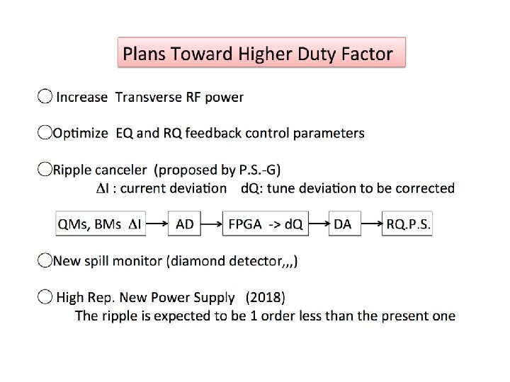
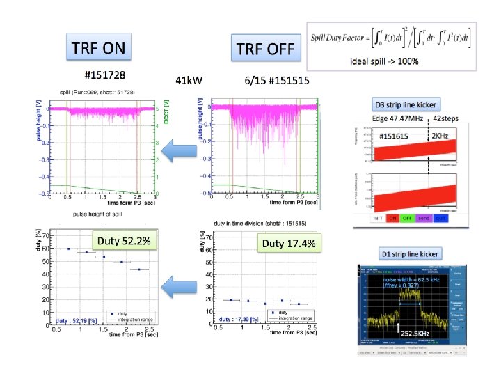
Feedbacks and spill quality • To correct macro and micro structure of the spill, 2 systems are operated in feedback with the extracted intensity: EQ and RQ • EQ used for the macro structure and RQ for the micro • Spill quality is increased using transverse RF kicks => 50 MHz • Used to pushed particles outside stable area • Duty factor almost tripled => 17 to 52% • Duty factor now usually in the range of 40 -60% Spill FFT

Dynamic Bump @ ESS @ SMS x’ x’ betatron phase +270° x ext. end ext. beginning x kick ESS Large angle spread @ ESS large beam loss SMS Small beam separation at SMS large beam loss 24

Dynamic Bump x’ Dynamic Bump Suppress angle spread by adjusting bump orbit synchronized with the betatron tune x beginning of extraction end of extraction kick ESS The tune is given by the main Quads and the servo quads, hence the function to apply to the bumpers current is a function of the Qs (main) and EQ/RQ (servo) quadrupoles. The control signal generated by the spill feedback system is used for this purpose 25

Effect of Dynamic Bump ESS Fixed Bump SMS 1 Position Distribution of Beam Loss Ext. Eff. 98. 6 % Time Dependence of Beam Loss Ext. ends Particle Number in MR Ext. starts 26

Effect of Dynamic Bump ESS Dynamic Bump SMS 1 Position Distribution of Beam Loss Ext. Eff. 99. 5 % Time Dependence of Beam Loss Ext. ends Particle Number in MR Ext. starts 27

Beam profiles and positon in the TL • Very high vacuum pressure permits to measure beam profiles all along the TL each shot • Beam positon at the target very stable and reproducible

Main problems • The main problem they are facing is the development of an instability 70/80 ms after the RF are switched off • They observed a rapid vacuum pressure increase when the debunching starts • For now, this was mitigated increasing the longitudinal emittance (injection with a phase offset)

Main problems • This also affected the SE losses significantly • Tried to increase chroma but PS limits reached • Other ideas to cure it: • RF gymnastic

What can we learn? • ES gaps larger than the maximum spiral step • Collimators in the extraction region to absorb scattered particles form ES • Chroma almost zero and amplitude based extraction, together with the dynamic bump, gives very small angular spread and hence small losses • Dynamic bump in operation since long time: extraction efficiency increased significantly • Difficult to obtain same results at the SPS due to extraction methodology • MD ideas: • Dynamic bump (as already proposed), SE using RF transverse noise for amplitude-based extraction (simulations needed first)

Conclusions • It was definitely a nice and very interesting experience! • They welcomed me very warmly and spent lots of time discussing and showing all they are working on • Quite some interesting things we can pick form them…at least try in MDs!

ELECTROSTATIC SEPTUM 33
 ~1 mm Electrolytic polished to remove burrs")
Cross Section of ESS Ribbon Material: W-Re(26%) ~1 mm Electrolytic polished to remove burrs 34

Measurement of the Ribbon Positions It is important to keep the deviation of the ribbons’ position small ESS 2 ESS 1 45μm 50μm Effective Thickness of the Ribbons = 30 + 50 μm 35

T 1 target Gold Target Gold et o Pr Cooling Water Ba er pp B n m a e se Copper Base Co Cooling Water Targ Current T 1 target can accept 50 k. W proton beam (will be upgraded up to ~ 100 k. W 36 in 2018)
- Slides: 38