Chapter 29 Magnetic Fields due to Currents Copyright


 29. 07")


 is a")


 shows a")


- Slides: 36
Chapter 29 Magnetic Fields due to Currents Copyright © 2014 John Wiley & Sons, Inc. All rights reserved.
29 -1 Magnetic Field due to a Current Learning Objectives 29. 01 Sketch a current-length element in a wire and indicate the direction of the magnetic field that it sets up at a given point near the wire. 29. 02 For a given point near a wire and a given current-element in the wire, determine the magnitude and direction of the magnetic field due to that element. 29. 03 Identify the magnitude of the magnetic field set up by a currentlength element at a point in line with the direction of that element. 29. 04 For a point to one side of a long straight wire carrying current, apply the relationship between the magnetic field magnitude, the current, and the distance to the point. 29. 05 For a point to one side of a long straight wire carrying current, use a right-hand rule to determine the direction of the magnetic field vector. 29. 06 Identify that around a long straight wire carrying current, the magnetic field lines form circles. © 2014 John Wiley & Sons, Inc. All rights reserved.
29 -1 Magnetic Field due to a Current Learning Objectives (Contd. ) 29. 07 For a point to one side of the end of a semi-infinite wire carrying current, apply the relationship between the magnetic field magnitude, the current, and the distance to the point. 29. 09 For a point to one side of a short straight wire carrying current, integrate the Biot– Savart law to find the magnetic field set up at the point by the current. 29. 08 For the center of curvature of a circular arc of wire carrying current, apply the relationship between the magnetic field magnitude, the current, the radius of curvature, and the angle subtended by the arc (in radians). © 2014 John Wiley & Sons, Inc. All rights reserved.
29 -1 Magnetic Field due to a Current The magnitude of the field d. B produced at point P at distance r by a current-length element ds turns out to be where θ is the angle between the directions of ds and ȓ, a unit vector that points from ds toward P. Symbol μ 0 is a constant, called the permeability constant, whose value is defined to be exactly The direction of d. B, shown as being into the page in the figure, is that of the cross product ds×ȓ. We can therefore write the above equation containing d. B in vector form as This vector equation and its scalar form are known as the law of Biot and Savart. © 2014 John Wiley & Sons, Inc. All rights reserved.
© 2014 John Wiley & Sons, Inc. All rights reserved.
© 2014 John Wiley & Sons, Inc. All rights reserved.
© 2014 John Wiley & Sons, Inc. All rights reserved.
29 -1 Magnetic Field due to a Current For a long straight wire carrying a current i, the Biot–Savart law gives, for the magnitude of the magnetic field at a perpendicular distance R from the wire, Figure: The magnetic field lines produced by a current in along straight wire form concentric circles around the wire. Here the current is into the page, as indicated by the X. The magnitude of the magnetic field at the center of a circular arc, of radius R and central angle ϕ (in radians), carrying current i, is © 2014 John Wiley & Sons, Inc. All rights reserved.
© 2014 John Wiley & Sons, Inc. All rights reserved.
© 2014 John Wiley & Sons, Inc. All rights reserved.
29 -2 Force Between Two Parallel Currents Learning Objectives 29. 10 Given two parallel or antiparallel currents, find the magnetic field of the first current at the location of the second current and then find the resulting force acting on that second current. 29. 11 Identify that parallel currents attract each other, and anti-parallel currents repel each other. 29. 12 Describe how a rail gun works. © 2014 John Wiley & Sons, Inc. All rights reserved.
© 2014 John Wiley & Sons, Inc. All rights reserved.
© 2014 John Wiley & Sons, Inc. All rights reserved.
29 -2 Force Between Two Parallel Currents Parallel wires carrying currents in the same direction attract each other, whereas parallel wires carrying currents in opposite directions repel each other. The magnitude of the force on a length L of either wire is where d is the wire separation, and ia and ib are the currents in the wires. The general procedure for finding the force on a current-carrying wire is this: Similarly, if the two currents were anti-parallel, we could show that the two wires repel each other. © 2014 John Wiley & Sons, Inc. All rights reserved. Two parallel wires carrying currents in the same direction attract each other. A rail gun, as a current i is set up in it. The current rapidly causes the conducting fuse to vaporize.
29 -3 Ampere’s Law Learning Objectives 29. 13 Apply Ampere’s law to a loop that encircles current. 29. 14 With Ampere’s law, use a right-hand rule for determining the algebraic sign of an encircled current. 29. 16 Apply Ampere’s law to a long straight wire with current, to find the magnetic field magnitude inside and outside the wire, identifying that only the current encircled by the Amperian loop matters. 29. 15 For more than one current within an Amperian loop, determine the net current to be used in Ampere’s law. © 2014 John Wiley & Sons, Inc. All rights reserved.
29 -3 Ampere’s Law Ampere’s law states that The line integral in this equation is evaluated around a closed loop called an Amperian loop. The current i on the right side is the net current encircled by the loop. Magnetic Fields of a long straight wire with current: Ampere’s law applied to an arbitrary Amperian loop that encircles two long straight wires but excludes a third wire. Note the directions of the currents. A right-hand rule for Ampere’s law, to determine the signs for currents encircled by an Amperian loop. © 2014 John Wiley & Sons, Inc. All rights reserved.
© 2014 John Wiley & Sons, Inc. All rights reserved.
© 2014 John Wiley & Sons, Inc. All rights reserved.
© 2014 John Wiley & Sons, Inc. All rights reserved.
© 2014 John Wiley & Sons, Inc. All rights reserved.
29 -4 Solenoids and Toroids Learning Objectives 29. 17 Describe a solenoid and a toroid and sketch their magnetic field lines. 29. 20 Explain how Ampere’s law is used to find the magnetic field inside a toroid. 29. 18 Explain how Ampere’s law is used to find the magnetic field inside a solenoid. 29. 21 Apply the relationship between a toroid’s internal magnetic field B, the current i, the radius r, and the total number of turns N. 29. 19 Apply the relationship between a solenoid’s internal magnetic field B, the current i, and the number of turns per unit length n of the solenoid. © 2014 John Wiley & Sons, Inc. All rights reserved.
29 -4 Solenoids and Toroids Magnetic Field of a Solenoid Figure (a) is a solenoid carrying current i. Figure (b) shows a section through a portion of a “stretched-out” solenoid. The solenoid’s magnetic field is the vector sum of the fields produced by the individual turns (windings) that make up the solenoid. For points very close to a turn, the wire behaves magnetically almost like a long straight wire, and the lines of B there almost concentric circles. Figure (b) suggests that the field tends to cancel between adjacent turns. It also suggests that, at points inside the solenoid and reasonably far from the wire, B is approximately parallel to the (central) solenoid axis. (a) (b) © 2014 John Wiley & Sons, Inc. All rights reserved.
© 2014 John Wiley & Sons, Inc. All rights reserved.
29 -4 Solenoids and Toroids Magnetic Field of a Solenoid Let us now apply Ampere’s law, to the ideal solenoid of Fig. (a), where B is uniform within the solenoid and zero outside it, using the rectangular Amperian loop abcda. We write as the sum of four integrals, one for each loop segment: (a) The first integral on the right of equation is Bh, where B is the magnitude of the uniform field B inside the solenoid and h is the (arbitrary) length of the segment from a to b. The second and fourth integrals are zero because for every element ds of these segments, B either is perpendicular to ds or is zero, and thus the product B ds is zero. The third integral, which is taken along a segment that lies outside the solenoid, is zero because B=0 at all external points. Thus, for the entire rectangular loop has the value Bh. Inside a long solenoid carrying current i, at points not near its ends, the magnitude B of the magnetic field is © 2014 John Wiley & Sons, Inc. All rights reserved.
© 2014 John Wiley & Sons, Inc. All rights reserved.
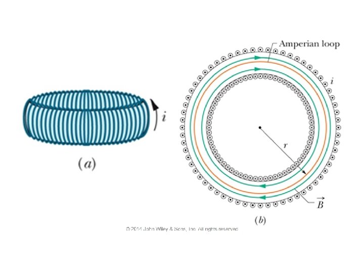
29 -4 Solenoids and Toroids Magnetic Field of a Toroid Figure (a) shows a toroid, which we may describe as a (hollow) solenoid that has been curved until its two ends meet, forming a sort of hollow bracelet. What magnetic field B is set up inside the toroid (inside the hollow of the bracelet)? We can find out from Ampere’s law and the symmetry of the bracelet. From the symmetry, we see that the lines of B form concentric circles inside the toroid, directed as shown in Fig. (b). Let us choose a concentric circle of radius r as an Amperian loop and traverse it in the clockwise direction. Ampere’s law yields where i is the current in the toroid windings (and is positive for those windings enclosed by the Amperian loop) and N is the total number of turns. This gives In contrast to the situation for a solenoid, B is not constant over the cross section of © 2014 John Wiley & Sons, Inc. All rights reserved. a toroid.
© 2014 John Wiley & Sons, Inc. All rights reserved.
© 2014 John Wiley & Sons, Inc. All rights reserved.
© 2014 John Wiley & Sons, Inc. All rights reserved.
29 -5 A Current-Carrying Coil as a Magnetic Dipole Learning Objectives 29. 22 Sketch the magnetic field lines of a flat coil that is carrying current. 29. 23 For a current-carrying coil, apply the relationship between the dipole moment magnitude μ and the coil’s current i, number of turns N, and area per turn A. 29. 24 For a point along the central axis, apply the relationship between the magnetic field magnitude B, the magnetic moment μ, and the distance z from the center of the coil. © 2014 John Wiley & Sons, Inc. All rights reserved.
29 -5 A Current-Carrying Coil as a Magnetic Dipole The magnetic field produced by a currentcarrying coil, which is a magnetic dipole, at a point P located a distance z along the coil’s perpendicular central axis is parallel to the axis and is given by Here μ is the dipole moment of the coil. This equation applies only when z is much greater than the dimensions of the coil. We have two ways in which we can regard a current-carrying coil as a magnetic dipole: (1) It experiences a torque when we place it in an external magnetic field. (2) It generates its own intrinsic magnetic field, given, for distant points along its axis, by the above equation. Figure shows the magnetic field of a current loop; one side of the loop acts as a north pole (in the direction of μ) © 2014 John Wiley & Sons, Inc. All rights reserved.
© 2014 John Wiley & Sons, Inc. All rights reserved.
© 2014 John Wiley & Sons, Inc. All rights reserved.
29 Summary The Biot-Savart Law • The magnetic field set up by a current- carrying conductor can be found from the Biot–Savart law. Magnetic Field of a Circular Arc • The magnitude of the magnetic field at the center of a circular arc, Eq. 29 -9 Eq. 29 -3 • The quantity μ 0, called the permeability constant, has the value Force Between Parallel Currents • The magnitude of the force on a length L of either wire is Magnetic Field of a Long Straight Wire • For a long straight wire carrying a current i, the Biot–Savart law gives, Eq. 29 -13 Ampere’s Law • Ampere’s law states that, Eq. 29 -4 © 2014 John Wiley & Sons, Inc. All rights reserved. Eq. 29 -14
29 Summary Fields of a Solenoid and a Toroid • Inside a long solenoid carrying current i, at points not near its ends, the magnitude B of the magnetic field is Eq. 29 -23 Field of a Magnetic Dipole • The magnetic field produced by a current-carrying coil, which is a magnetic dipole, at a point P located a distance z along the coil’s perpendicular central axis is parallel to the axis and is given by • At a point inside a toroid, the magnitude B of the magnetic field is Eq. 29 -24 © 2014 John Wiley & Sons, Inc. All rights reserved. Eq. 29 -9