Magnetic Fields due to Currents Chapter 29 Magnetic


")
")


, the B-field lines are directed opposite")
 is a solenoid carrying")
 The first integral on the right of equation is Bh,")
")
 shows a toroid, which")


- Slides: 44
Magnetic Fields due to Currents Chapter 29
Magnetic Field Due to a Current
Magnetic Field Due to a Current
Magnetic Field Due to a Current
Magnetic Field due to a Current
Magnetic Field due to a Current For a long straight wire carrying a current i, the Biot– Savart law gives, for the magnitude of the magnetic field at a perpendicular distance R from the wire,
Magnetic Field due to a Current
Magnetic Field due to a Current in a Circular Arc The magnitude of the magnetic field at the center of a circular arc, of radius R and central angle ϕ (in radians), carrying current i, is Heads Up. Note that this equation gives us the magnetic field only at the center of curvature of a circular arc of current. When you insert data into the equation, you must be careful to express ϕ in radians rather than degrees. For example, to find the magnitude of the magnetic field at the center of a full circle of current, you would substitute 2 p rad for ϕ, finding
Concept Check – Current-Carrying Wire If the current in this wire is into the page, what is the direction of the magnetic field at point P? 1 P 4 2 3
Concept Check – Current-Carrying Wire If the current in this wire is into the page, what is the direction of the magnetic field at point P? 1 P 4 2 3 Using the right-hand rule to determine the direction of the magnetic field around a wire, the magnetic field will point in the clockwise direction.
Concept Check – Current-Carrying Wire If the currents in this wire is out of the page, what is the direction of the magnetic field at point P? 1 P 4 2 3
Concept Check – Current-Carrying Wire If the currents in this wire is out of the page, what is the direction of the magnetic field at point P? 1 P 4 2 3 Using the right-hand rule to determine the direction of the magnetic field around a wire, the magnetic field will point in the counter-clockwise direction.
Concept Check – Current-Carrying Wire If the currents in these wires have the same magnitude but opposite directions, what is the direction of the magnetic field at point P? 1 P 4 2 3
Concept Check – Current-Carrying Wire If the currents in these wires have the same magnitude but opposite directions, what is the direction of the magnetic field at point P? 1 P 4 2 3 Using the right-hand rule, we can sketch the B fields due to the two currents. Adding them up as vectors gives a total magnetic field pointing downward
Concept Check – Current Loop What is the direction of the magnetic field at the center (point P) of the square loop of current? 1. left 2. right 3. zero 4. into the page 5. out of the page I P
Concept Check – Current Loop What is the direction of the magnetic field at the center (point P) of the square loop of current? 1. left 2. right 3. zero 4. into the page 5. out of the page I P Use the right-hand rule for each wire segment to find that each segment has its B field pointing out of the page at point P. So, there will be an N pole in front of the page and an S pole behind the page.
Concept Check – Current-Carrying Wire Each of the wires in the figures below carry the same current, either into or out of the page. In which case is the magnetic field at the center of the square greatest? 1 B=? 4. same for all 2 B=? 3 B=?
Concept Check – Current-Carrying Wire Each of the wires in the figures below carry the same current, either into or out of the page. In which case is the magnetic field at the center of the square greatest? 1 B=? 4. same for all 2 B=? 3 B=?
Sample Problem 29. 01
Sample Problem 29. 02
Force Between Two Parallel Currents Parallel wires carrying currents in the same direction attract each other, whereas parallel wires carrying currents in opposite directions repel each other. The magnitude of the force on a length L of either wire is where d is the wire separation, and ia and ib are the currents in the wires. The general procedure for finding the force on a current-carrying wire is this: Similarly, if the two currents were anti-parallel, we could show that the two wires repel each other. Two parallel wires carrying currents in the same direction attract each other. A rail gun, as a current i is set up in it. The current rapidly causes the conducting fuse to vaporize.
Two Parallel Wires MIT simulation – Two wires with parallel current MIT Simulation – Two wires with antiparallel current
Concept Check – Parallel Wires Two straight wires run parallel to each other, each carrying a current in the direction shown below. The two wires experience a force in which direction? 1. toward each other 2. away from each other 3. there is no force
Concept Check – Parallel Wires Two straight wires run parallel to each other, each carrying a current in the direction shown below. The two wires experience a force in which direction? 1. toward each other 2. away from each other 3. there is no force The current in each wire produces a magnetic field that is felt by the current of the other wire. Using the right-hand rule, we find that each wire experiences a force toward the other wire (i. e. , an attractive force) force when the currents are parallel
Ampere’s Law Ampere’s law states that The line integral in this equation is evaluated around a closed loop called an Amperian loop. The current i on the right side is the net current encircled by the loop. Ampere’s law applied to an arbitrary Amperian loop that encircles two long straight wires but excludes a third wire. Note the directions of the currents. A right-hand rule for Ampere’s law, to determine the signs for currents encircled by an Amperian loop.
Ampere’s Law Ampere’s law applied to an arbitrary Amperian loop that encircles two long straight wires but excludes a third wire. Note the directions of the currents. A right-hand rule for Ampere’s law, to determine the signs for currents encircled by an Amperian loop.
Ampere’s Law A right-hand rule for Ampere’s law, to determine the signs for currents encircled by an Amperian loop. We don’t have enough information to evaluate the integral and solve for B. However, we will look at some situations where symmetry allows us to simplify and solve.
Ampere’s Law Magnetic Fields of a long straight wire with current (outside the wire)
Ampere’s Law Magnetic Fields of a long straight wire with current (inside the wire)
Ampere’s Law d; tie between a and c; then b
Sample 29. 03
Sample 29. 03 Since our value is (-), the B-field lines are directed opposite our direction of integration (ccw).
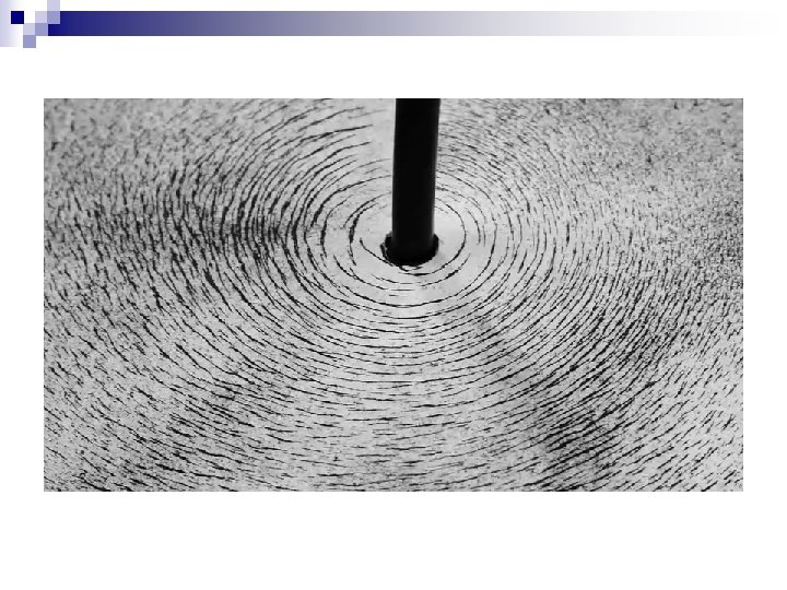
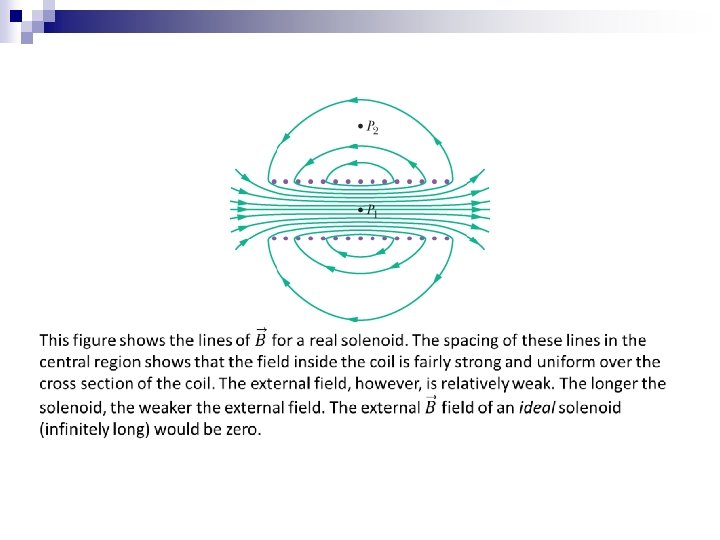
Solenoids and Toroids Magnetic Field of a Solenoid Figure (a) is a solenoid carrying current i. Figure (b) shows a section through a portion of a “stretched-out” solenoid. The solenoid’s magnetic field is the vector sum of the fields produced by the individual turns (windings) that make up the solenoid. For points very close to a turn, the wire behaves magnetically almost like a long straight wire, and the lines of B there almost concentric circles. Figure (b) suggests that the field tends to cancel between adjacent turns. It also suggests that, at points inside the solenoid and reasonably far from the wire, B is approximately parallel to the (central) solenoid axis. (a) (b)
Solenoids and Toroids (a) The first integral on the right of equation is Bh, where B is the magnitude of the uniform field B inside the solenoid and h is the (arbitrary) length of the segment from a to b. The second and fourth integrals are zero because for every element ds of these segments, B either is perpendicular to ds or is zero, and thus the product B ds is zero. The third integral, which is taken along a segment that lies outside the solenoid, is zero because B=0 at all external points.
Solenoids and Toroids (a)
Solenoids and Toroids Magnetic Field of a Toroid Figure (a) shows a toroid, which we may describe as a (hollow) solenoid that has been curved until its two ends meet, forming a sort of hollow bracelet. What magnetic field B is set up inside the toroid (inside the hollow of the bracelet)? We can find out from Ampere’s law and the symmetry of the bracelet. From the symmetry, we see that the lines of B form concentric circles inside the toroid, directed as shown in Fig. (b). Let us choose a concentric circle of radius r as an Amperian loop and traverse it in the clockwise direction. Ampere’s law yields where i is the current in the toroid windings (and is positive for those windings enclosed by the Amperian loop) and N is the total number of turns. This gives In contrast to the situation for a solenoid, B is not constant over the cross section of a toroid.
Sample Problem 29. 04
A Current-Carrying Coil as a Magnetic Dipole
Current Loop N S
Current Loop
Summary The Biot-Savart Law • The magnetic field set up by a current- carrying conductor can be found from the Biot–Savart law. Magnetic Field of a Circular Arc • The magnitude of the magnetic field at the center of a circular arc, Eq. 29 -9 Eq. 29 -3 • The quantity μ 0, called the permeability constant, has the value Force Between Parallel Currents • The magnitude of the force on a length L of either wire is Magnetic Field of a Long Straight Wire • For a long straight wire carrying a current i, the Biot–Savart law gives, Eq. 29 -4 Eq. 29 -13 Ampere’s Law • Ampere’s law states that, Eq. 29 -14
Summary Fields of a Solenoid and a Toroid • Inside a long solenoid carrying current i, at points not near its ends, the magnitude B of the magnetic field is Eq. 29 -23 • At a point inside a toroid, the magnitude B of the magnetic field is Eq. 29 -24 Field of a Magnetic Dipole • The magnetic field produced by a current-carrying coil, which is a magnetic dipole, at a point P located a distance z along the coil’s perpendicular central axis is parallel to the axis and is given by Eq. 29 -9