Chapter 14 Lateral Earth Pressure Curved Failure Surface


 -")
 Soil")
 Soil")
 -")
 4.")
 - Proposed the curved failure surface")


 - Two Types of Braced Cuts Soldier beam,")


- Slides: 30
Chapter 14 Lateral Earth Pressure – Curved Failure Surface 연세대학교 지반공학연구실 Soil Substructure Interaction Lab.
14. 1 Retaining Walls with Friction Soil Substructure Interaction Lab.
14. 1 Retaining Walls with Friction downward motion of the soil relative to the wall Soil Substructure Interaction Lab.
14. 1 Retaining Walls with Friction downward motion of the wall relative to the soil Substructure Interaction Lab.
upward motion of the soil relative to the wall Soil Substructure Interaction Lab.
14. 1 Retaining Walls with Friction upward motion of the wall relative to the soil Substructure Interaction Lab.
14. 2 Properties of a Logarithmic Spiral logarithmic spiral의 성질 Location of centroid Soil Substructure Interaction Lab.
14. 3 Procedure for Determination of Passive Earth Pressure, Pp (Cohesionless Backfill ) - procedure of evaluating the passive resistance by trial wedges (Terzaghi & Peck. 1967) Soil Substructure Interaction Lab.
14. 3 Procedure for Determination of Passive Earth Pressure, Pp (Cohesionless Backfill ) Soil Substructure Interaction Lab.
14. 3 Procedure for Determination of Passive Earth Pressure, Pp (Cohesionless Backfill ) Soil Substructure Interaction Lab.
14. 3 Procedure for Determination of Passive Earth Pressure, Pp (Cohesionless Backfill ) - procedure of evaluating the passive resistance by trial wedges (Terzaghi & Peck. 1967) Steps 1. Draw retaining wall to a convenient scale 2. Draw line C 1 A (45 - /2) degrees with the surface of the backfill 3. Consider the stability of the soil mass ABC 1 C 1 for equilibrium) Rankine’s passive force F 1 = resultant of the shear and normal forces P 1 = passive force per unit length of the wall Soil Substructure Interaction Lab.
14. 3 Procedure for Determination of Passive Earth Pressure, Pp (Cohesionless Backfill ) 4. + 5. Trial passive force per unit length of the wall is repeated for several trial wedges 6. P 1 (trial wedge 1) P 2 (trial wedge 2) Plotted to a same scale P 3 (trial wedge n) • Find the low point of the smooth curve • That is actual passive force, Pp Soil Substructure Interaction Lab.
14. 4 Coeffi. of Passive Earth Pressure (Kp) - Proposed the curved failure surface like as arc. of a logarithmic spiral (Terzaghi & Peck, 1967 : Janbu, 1957) arc. of an ellipse (Caquot & Kerisel, 1948) ; Fig. 14. 4 , Table 14. 1 참조 arc. of a circle (Packshaw, 1969) Passive Presure by the Method of Slices by Shields and Tolunay (1973) Table 14. 2 참조 Example 14. 1 Soil Substructure Interaction Lab.
14. 5 Passive Force on Walls with Earthquake Forces H Arc of a log spiral Logarithmic spiral failure surface for determination of Ppe Soil Substructure Interaction Lab.
14. 5 Passive Force on Walls with Earthquake Forces The passive force, Figure 14. 6 shows variation of with and for Mononobe-Okabe solution and for the logarithmic spiral Type of failure surface analysis. Soil Substructure Interaction Lab.
14. 5 Passive Force on Walls with Earthquake Forces Soil Substructure Interaction Lab.
14. 5 Passive Force on Walls with Earthquake Forces As we can see from the figure, for a given value of the magnitude of , is always larger when the failure surface is assumed to be plane (Mononobe-Okabe solution) Soil Substructure Interaction Lab.
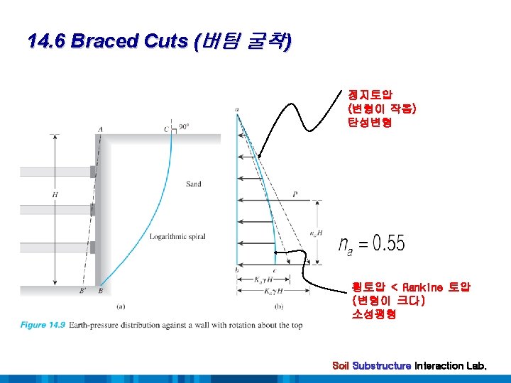
14. 6 Braced Cuts (버팀 굴착) - Two Types of Braced Cuts Soldier beam, wood lagging, wale, strut Sheetpile, wale, strut Soil Substructure Interaction Lab.
14. 7 Determination of Active Thrust on Bracing Systems of Open Cuts in Granular soil - Active thrust on the bracing system of open cuts : Terzaghi’s general wedge theory (1941) General Procedures 1. A point b 1 is selected. 2. From b 1, a line b 1 b 1 that makes an angle of with the ground surface is drawn. 3. The arc. of the logarithmic spiral, b 1 B is drawn with the center of the spiral (pt. O 1) 4. Consider the stability of the soil mass ABb 1 for equilibrium. W 1 = · area(ABb 1)·(1) P 1 = the active trust acting at a point na·H F 1 = the resultant of the shear and normal forces acting along with the trial failure surface. Soil Substructure Interaction Lab.
14. 7 Determination of Active Thrust on Bracing Systems of Open Cuts in Granular soil + 6. Trial active thrust is repeated for several trial wedges P 1 (trial wedge 1) P 2 (trial wedge 2) Plotted to a same scale Pn (trial wedge n) Find the maximum point of the smooth curve That is actual active force, Pa Soil Substructure Interaction Lab.
14. 7 Determination of Active Thrust on Bracing Systems of Open Cuts in Granular soil Substructure Interaction Lab.
14. 7 Determination of Active Thrust on Bracing Systems of Open Cuts in Granular soil Substructure Interaction Lab.
14. 8 Determination of Active Thrust on Bracing Systems for Cuts in Cohesive Soil - Undrained condition, =0 The equation of the logarithmic spiral (circle) 1. Consider force for equilibrium of the wedge ABb 1 W 1 = · area(ABb 1)·(1) P 1 = the active trust acting at a height of na·H F 1 = the resultant acting along the surface of sliding cur 1 1 = force from cohesion acting along the surface of sliding ca. H = force from adhesion between the soil and the sheeting Soil Substructure Interaction Lab.
14. 8 Determination of Active Thrust on Bracing Systems for Cuts in Cohesive Soil 2. + 3. Trial active thrusts is obtained from several trial wedges P 1 (trial wedge 1) P 2 (trial wedge 2) Pn (trial wedge n) Plotted to a same scale the highest point of the smooth curve That is actual active thrust, Pa Soil Substructure Interaction Lab.
14. 8 Determination of Active Thrust on Bracing Systems for Cuts in Cohesive Soil Substructure Interaction Lab.
14. 8 Determination of Active Thrust on Bracing Systems for Cuts in Cohesive Soil H Determination of active force on bracing system of open cut in cohesive soil( =0) Soil Substructure Interaction Lab.
14. 9 Pressure Variation for Design of Sheetings, Struts, and Wales - Calculation using general wedge theory does not explain the veriation of the earth PR with depth - Empirical lateral PR. diagrams (Peck, 1969) Soil Substructure Interaction Lab.
14. 9 Pressure Variation for Design of Sheetings, Struts, and Wales - Limitation for Pressure Envelopes 1. PR. envelopes : apparent PR. envelopes 2. applied depth 20 ( 6 m) 3. W. T. : below the bottom of the cut 4. Sand : assumed to be drained 5. Clay : assumed to be undrained and pwp is not considered Strut load determination - Soldier piles are assumed to be hinged at the strut level, except for the top & bottom ones - Strut loads Soil Substructure Interaction Lab.
14. 9 Pressure Variation for Design of Sheetings, Struts, and Wales Soil Substructure Interaction Lab.