Challenges of Single Event Upset and Transient Testing

- Slides: 31
Challenges of Single Event Upset and Transient Testing and Characterization of Mixed Signal Products Kirby Kruckmeyer
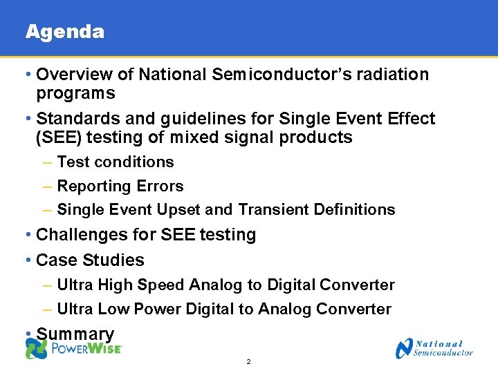
Agenda • Overview of National Semiconductor’s radiation programs • Standards and guidelines for Single Event Effect (SEE) testing of mixed signal products – Test conditions – Reporting Errors – Single Event Upset and Transient Definitions • Challenges for SEE testing • Case Studies – Ultra High Speed Analog to Digital Converter – Ultra Low Power Digital to Analog Converter • Summary 2
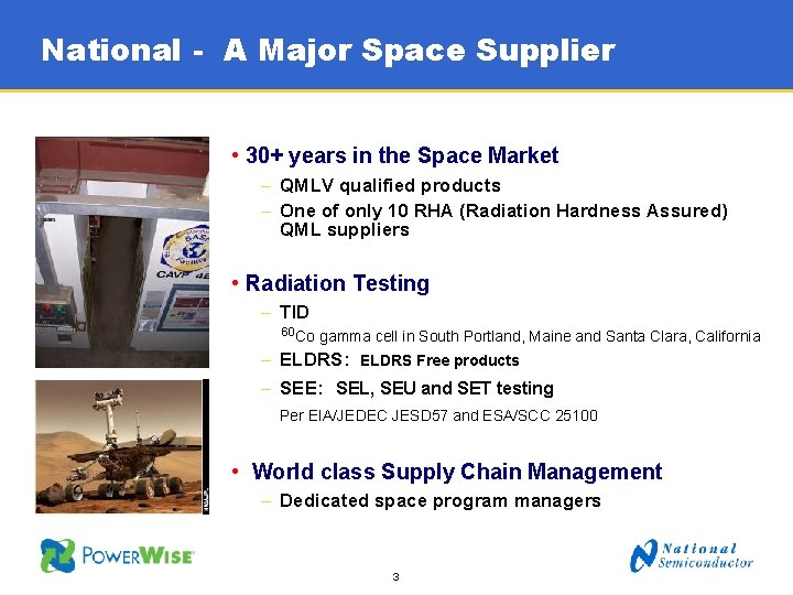
National - A Major Space Supplier • 30+ years in the Space Market – QMLV qualified products – One of only 10 RHA (Radiation Hardness Assured) QML suppliers • Radiation Testing – TID 60 Co gamma cell in South Portland, Maine and Santa Clara, California – ELDRS: ELDRS Free products – SEE: SEL, SEU and SET testing Per EIA/JEDEC JESD 57 and ESA/SCC 25100 • World class Supply Chain Management – Dedicated space program managers 3
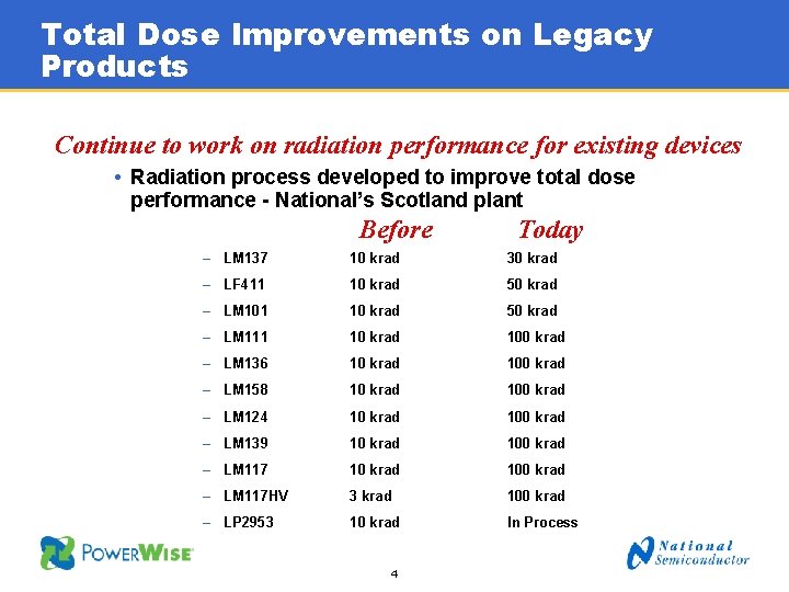
Total Dose Improvements on Legacy Products Continue to work on radiation performance for existing devices • Radiation process developed to improve total dose performance - National’s Scotland plant Before Today – LM 137 10 krad 30 krad – LF 411 10 krad 50 krad – LM 101 10 krad 50 krad – LM 111 10 krad 100 krad – LM 136 10 krad 100 krad – LM 158 10 krad 100 krad – LM 124 10 krad 100 krad – LM 139 10 krad 100 krad – LM 117 HV 3 krad 100 krad – LP 2953 10 krad In Process 4
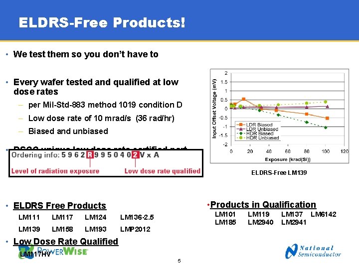
ELDRS-Free Products! • We test them so you don’t have to • Every wafer tested and qualified at low dose rates – per Mil-Std-883 method 1019 condition D – Low dose rate of 10 mrad/s (36 rad/hr) – Biased and unbiased • DSCC unique low dose rate certified part numbers ELDRS-Free LM 139 • Products in Qualification • ELDRS Free Products LM 111 LM 117 LM 124 LM 136 -2. 5 LM 139 LM 158 LM 193 LMP 2012 LM 101 LM 185 • Low Dose Rate Qualified LM 117 HV 5 LM 119 LM 2940 LM 137 LM 6142 LM 2941
National is more than just the LM 124 Recent New Product Releases: • ADC 08 D 1000 WGFQV 1 GS/s 8 bit Analog to Digital Converter • ADC 08 D 1520 WGFQV 1. 5 GS/s 8 bit Analog to Digital Converter • ADC 128 S 102 WGRQV General Purpose 12 bit Analog to Digital Converter – m. W Power • DAC 121 S 101 WGRQV General Purpose 12 bit Digital to Analog Converter – m. W Power • LMP 2012 WGLQMLV Precision Rail to Rail Operational Amplifier • ADC 14155 WGRQV 155 MS/s 14 bit Analog to Digital Converter 6
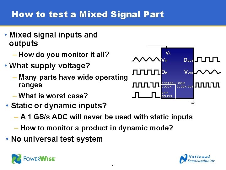
How to test a Mixed Signal Part • Mixed signal inputs and outputs VA – How do you monitor it all? • What supply voltage? – Many parts have wide operating ranges – What is worst case? VIN DOUT DIN VOUT CONTROL LOGIC CLOCK OUT CHIP SELECT • Static or dynamic inputs? – A 1 GS/s ADC will never be used with static inputs – How to monitor a product in dynamic mode? • No universal test system 7
Testing Guidance. Limited For Mixed Signal Products • Test development typically starts with FPGA’s and memories, then moves to analog parts. Mixed signal products are usually an afterthought – Sandia proton spec in development - using memories as driver – NASA new SEE guidelines (digitally oriented) and Linear SEE Testing Guidelines • Standards – Oriented towards digital products – EIA/JEDEC Standard JESD 57 • Only mentions bit flips; no guidance on analog outputs or transients • No mention of mixed signal products – ASTM Standard Guide F 1192 – 00 • Two definitions for transients, but no guidance on testing for them • No mention of mixed signal products – ESA/SCC Basic Specification 25100 • “Analogue and mixed analogue/digital technologies may generate false outputs or transients as the result of SEE. Test system shall be capable of monitoring and logging these effects. ” 8
How to Report the Results? - Digital Is it “errors per bit” or some other measure? • “Errors per bit” is a standard metric for digital product – Customers put “errors per bit” in PO’s for all kinds of products – Some datasheets report “errors per bit” on products like PLL’s • Does not make sense for most mixed signal products? – What is a bit in a PLL? – ADC bits have varying values and impact • ADC: should be reported as complete “code errors” • PLL’s and clocks: should be reported as output “error rate” 9
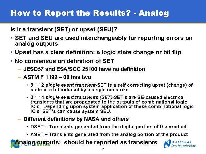
How to Report the Results? - Analog Is it a transient (SET) or upset (SEU)? • SET and SEU are used interchangeably for reporting errors on analog outputs • Upset has a clear definition: a logic state change or bit flip • No consensus on definition of SET – JESD 57 and ESA/SCC 25100 have no definition – ASTM F 1192 – 00 has two • 3. 1. 12 single event transient-SET is a self correcting upset (change) of state of a bit induced by a single ion strike. • 3. 1. 14 single event transients (SET)-SET’s are SE-caused electrical transients that are propagated to the outputs of combinational logic IC’s. Depending upon system application of these combinational logic IC’s, SET’s can cause system SEU. – Different definitions by NASA and others • DSET – Transients generated from the digital portion of the product • ASET – Transients generated from the analog portion of the product • Analog outputs: should be reported as transients 10
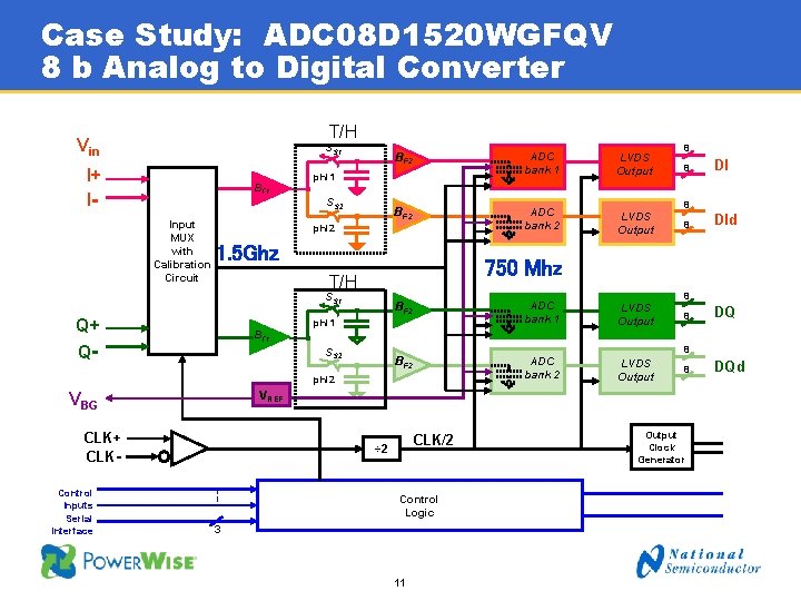
Case Study: ADC 08 D 1520 WGFQV 8 b Analog to Digital Converter T/H Vin SS 1 I+ I- Bf 1 ADC bank 1 LVDS Output BF 2 ADC bank 2 LVDS Output phi 1 SS 2 Input MUX with Calibration Circuit BF 2 phi 2 1. 5 Ghz SS 1 DI 8 BF 2 ADC bank 1 LVDS Output BF 2 ADC bank 2 LVDS Output phi 1 8 DId 8 8 DQ Bf 1 SS 2 phi 2 8 8 VREF VBG CLK+ CLKControl Inputs Serial Interface 8 750 Mhz T/H Q+ Q- 8 CLK/2 ÷ 2 Control Logic 3 11 Output Clock Generator DQd
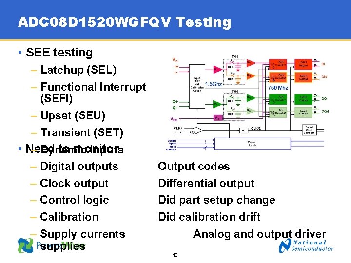
ADC 08 D 1520 WGFQV Testing • SEE testing – Latchup (SEL) – Functional Interrupt (SEFI) – Upset (SEU) – Transient (SET) • Need to monitor – Dynamic Inputs – Digital outputs – Clock output – Control logic – Calibration – Supply currents supplies Output codes Differential output Did part setup change Did calibration drift Analog and output driver 12
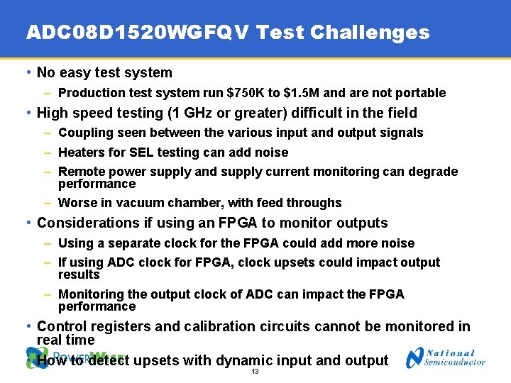
ADC 08 D 1520 WGFQV Test Challenges • No easy test system – Production test system run $750 K to $1. 5 M and are not portable • High speed testing (1 GHz or greater) difficult in the field – Coupling seen between the various input and output signals – Heaters for SEL testing can add noise – Remote power supply and supply current monitoring can degrade performance – Worse in vacuum chamber, with feed throughs • Considerations if using an FPGA to monitor outputs – Using a separate clock for the FPGA could add more noise – If using ADC clock for FPGA, clock upsets could impact output results – Monitoring the output clock of ADC can impact the FPGA performance • Control registers and calibration circuits cannot be monitored in real time • How to detect upsets with dynamic input and output 13
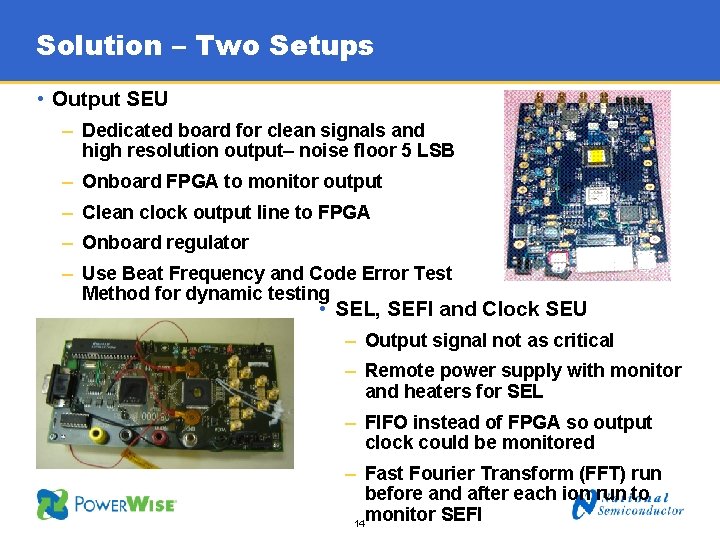
Solution – Two Setups • Output SEU – Dedicated board for clean signals and high resolution output– noise floor 5 LSB – Onboard FPGA to monitor output – Clean clock output line to FPGA – Onboard regulator – Use Beat Frequency and Code Error Test Method for dynamic testing • SEL, SEFI and Clock SEU – Output signal not as critical – Remote power supply with monitor and heaters for SEL – FIFO instead of FPGA so output clock could be monitored – Fast Fourier Transform (FFT) run before and after each ion run to monitor SEFI 14
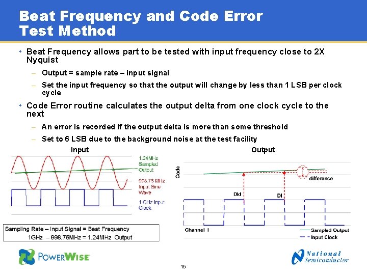
Beat Frequency and Code Error Test Method • Beat Frequency allows part to be tested with input frequency close to 2 X Nyquist – Output = sample rate – input signal – Set the input frequency so that the output will change by less than 1 LSB per clock cycle • Code Error routine calculates the output delta from one clock cycle to the next – An error is recorded if the output delta is more than some threshold – Set to 6 LSB due to the background noise at the test facility Input Output 15
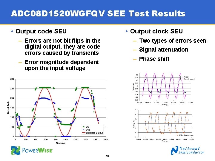
ADC 08 D 1520 WGFQV SEE Test Results • Output code SEU • Output clock SEU – Errors are not bit flips in the digital output, they are code errors caused by transients – Two types of errors seen – Signal attenuation – Phase shift – Error magnitude dependent upon the input voltage 16
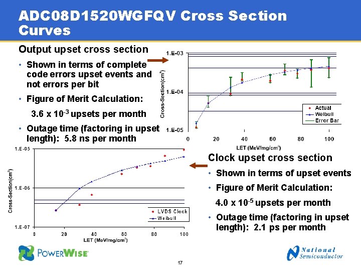
ADC 08 D 1520 WGFQV Cross Section Curves Output upset cross section • Shown in terms of complete code errors upset events and not errors per bit • Figure of Merit Calculation: 3. 6 x 10 -3 upsets per month • Outage time (factoring in upset length): 5. 8 ns per month Clock upset cross section • Shown in terms of upset events • Figure of Merit Calculation: 4. 0 x 10 -5 upsets per month • Outage time (factoring in upset length): 2. 1 ps per month 17
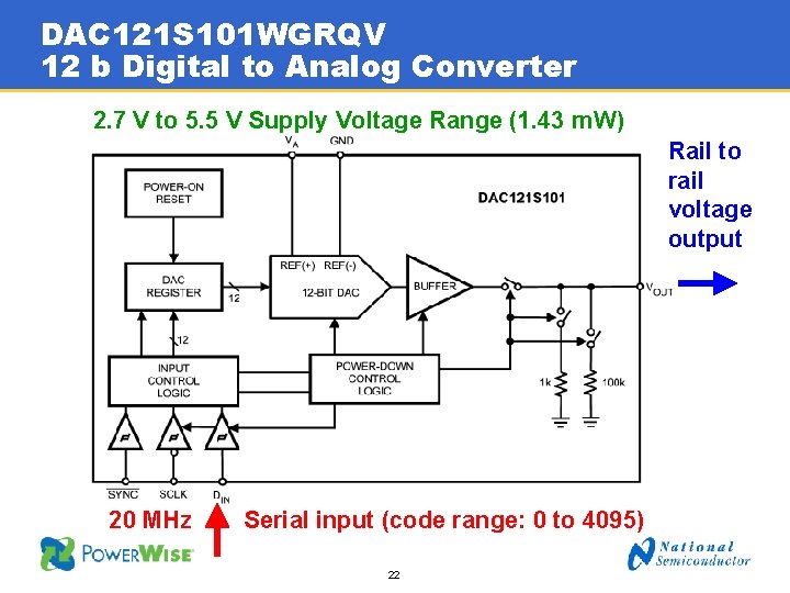
Case study: DAC 121 S 101 WGRQV 12 b Digital to Analog Converter • How should a Digital to Analog Converter be tested? • What operating conditions cause the worst case? – Cross section – Transient amplitude and pulse width • Operating conditions? – Supply voltage – Inputs 18
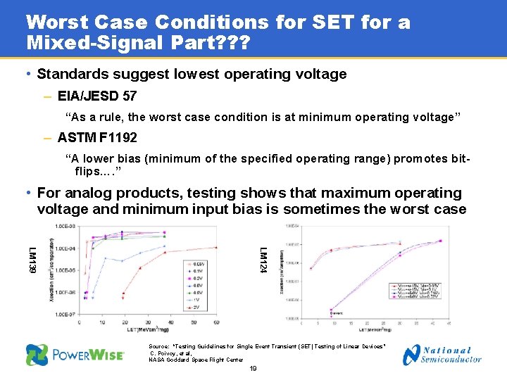
Worst Case Conditions for SET for a Mixed-Signal Part? ? ? • Standards suggest lowest operating voltage – EIA/JESD 57 “As a rule, the worst case condition is at minimum operating voltage” – ASTM F 1192 “A lower bias (minimum of the specified operating range) promotes bitflips…. ” • For analog products, testing shows that maximum operating voltage and minimum input bias is sometimes the worst case LM 124 LM 139 Source: “Testing Guidelines for Single Event Transient (SET) Testing of Linear Devices” C. Poivoy, et al, NASA Goddard Space Flight Center 19
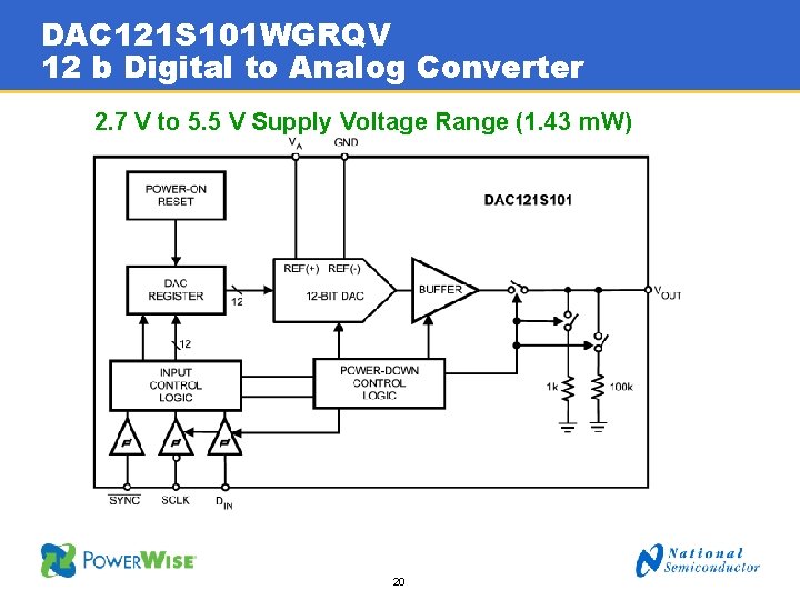
DAC 121 S 101 WGRQV 12 b Digital to Analog Converter 2. 7 V to 5. 5 V Supply Voltage Range (1. 43 m. W) 20
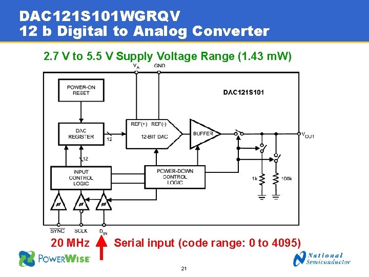
DAC 121 S 101 WGRQV 12 b Digital to Analog Converter 2. 7 V to 5. 5 V Supply Voltage Range (1. 43 m. W) 20 MHz Serial input (code range: 0 to 4095) 21
DAC 121 S 101 WGRQV 12 b Digital to Analog Converter 2. 7 V to 5. 5 V Supply Voltage Range (1. 43 m. W) Rail to rail voltage output 20 MHz Serial input (code range: 0 to 4095) 22
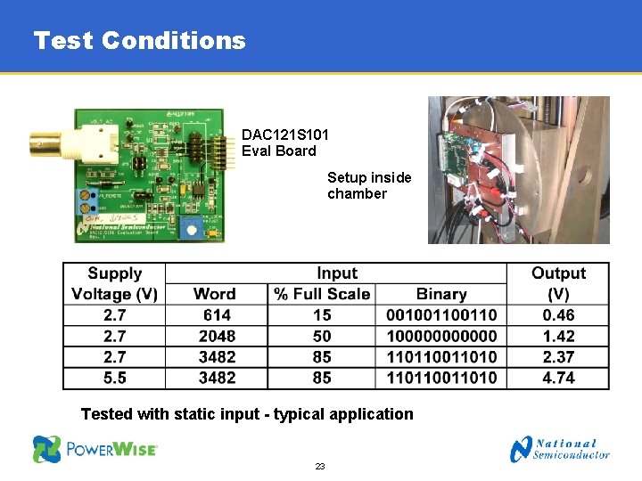
Test Conditions DAC 121 S 101 Eval Board Setup inside chamber Tested with static input - typical application 23
Dependence on Supply Voltage SET Cross Section vs. LET for input code = 3482 24
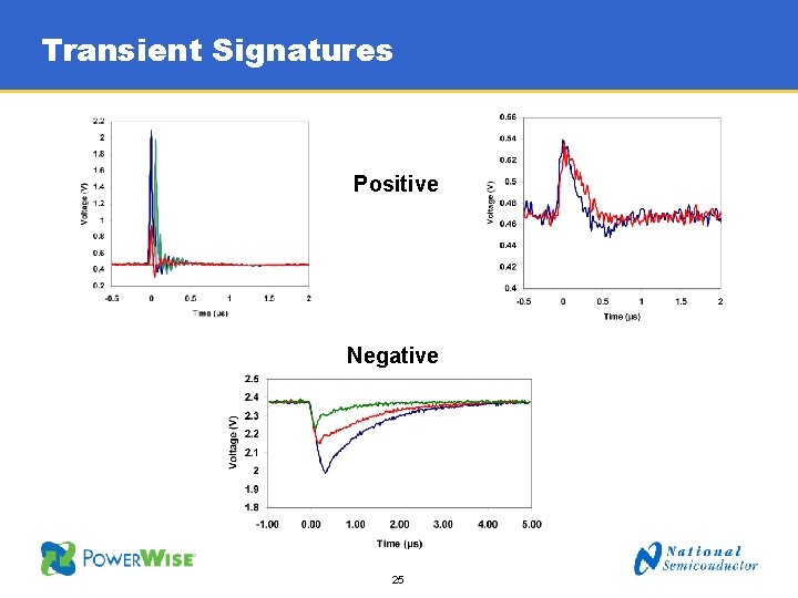
Transient Signatures Positive Negative 25
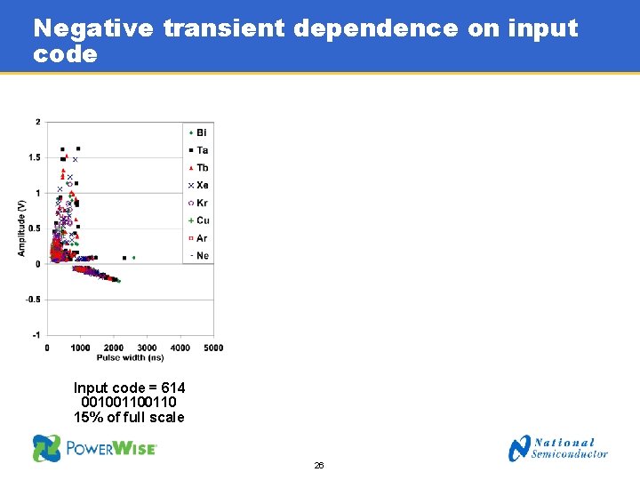
Negative transient dependence on input code Input code = 614 00100110 15% of full scale 26
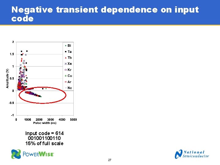
Negative transient dependence on input code Input code = 614 00100110 15% of full scale 27
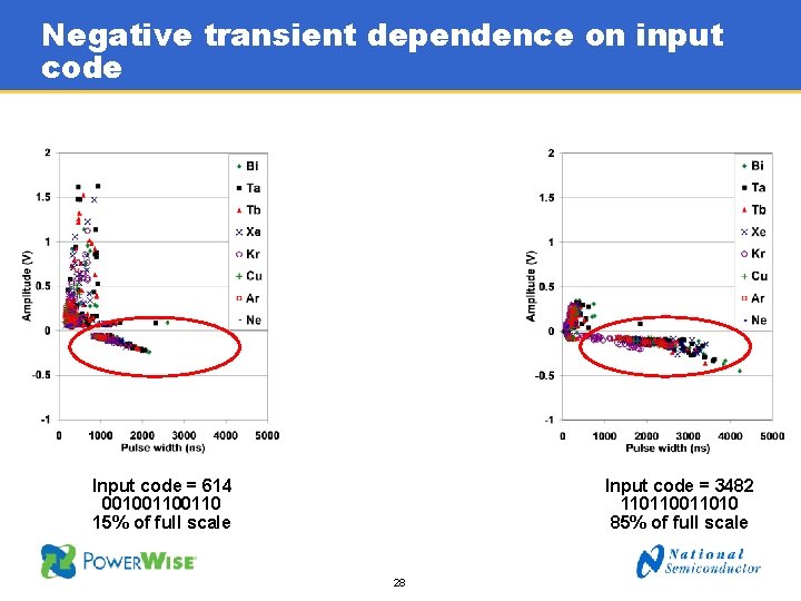
Negative transient dependence on input code Input code = 3482 11011010 85% of full scale Input code = 614 00100110 15% of full scale 28
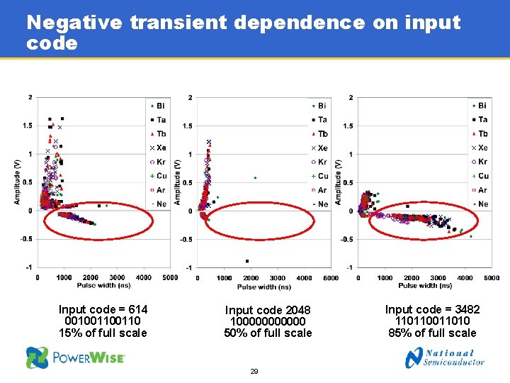
Negative transient dependence on input code Input code = 614 00100110 15% of full scale Input code 2048 1000000 50% of full scale 29 Input code = 3482 11011010 85% of full scale
Summary • Testing mixed signal products can be complex and challenging • There are very few standards or guidelines for testing mixed signal products • Some unique test methods are needed • Mixed signal Single Event Transient and Upset responses can be very different than for either pure digital or pure analog products • It is necessary to characterize a product over all application conditions that will be used 30
31