Forging Forging Forging denotes a family of process


 Open-die forging")
 Impression-die forging")
 Flashless forging")
 between two flat dies and")


 Start of process with workpiece at its")


 Just prior to initial contact with raw workpiece, (2) partial")


 • In closed-die forging, no flash is formed and")
 • Requires: § Special and more complex dies §")
 Ø Compression of work in punch and die tooling")
 Just before contact with work piece, (2) partial compression, and")


")


 Examples of heading (upset forging) operations: (a) heading a nail using")
 (a) Heading operation, to form heads on fasteners such as nails")


 Swaging of tubes without")


Production of steel balls by the skew-rolling process. (b)Production of steel balls")

 to remove the flash after")


 Labs formed by web buckling")


 The")


 The")
 - Draft angles q. Draft angle, in metal manufacturing processes, is")
 Draft")
 Die")


 in an open-die forging operation on")


 True Stress-True Strain Curves Figure 2. 6 True")

- Slides: 135
Forging
Forging • Forging denotes a family of process to make discrete parts in which plastic deformation take place by compressive forces applied through various dies and tooling Ø forging is one of the Oldest metalworking operations known, dating back too 5000 B. C and used in making parts with a wide range of sizes and shapes and from a variety of material. Ø Simple forgings can be made with a heavy hammer and an anvil by techniques practiced by blacksmiths for centuries. Ø Typical parts, now mostly made on modern machinery and at high production rates are : automotive engine components, [engine crankshafts, connecting rods, gears], turbine disc, Aircraft structural components, jet engin, turbine parts • Also, basic metals industries use forging to establish basic shape of large and small parts that are subsequently machined to final geometry and size • The forging process can produce parts that are in the category of net-shape manufacturing.
Forging What is forging? A compressive force is applied to the metal with a hammer to give it the required shape Modern Components: engine crankshafts, connecting rods, gears, aircraft structural components, jet engine turbine parts. Classified by working temperature: • Hot or warm forging – most common, high deformation, lowers the strength but increases ductility of the forged part. • Cold forging –advantage: increased strength due to strain hardening. Classified by type of load: • Forge hammer (impact) - applies an impact load. • Forge press (press) - applies gradual pressure.
Products of forging Connecting rods Engine crankshafts Aircraft structural components
Products of forging Jet engine turbine parts Basic shape of small parts
Forging q. Forging refines the microstructure of the metal, eliminates the hidden defects such as hair cracks and voids, and rearranges the fibrous macrostructure to conform with the metal flow. By successful design of the dies, the metal flow during the process can be employed to promote the alignment of the fibers with the anticipated direction of maximum stress.
Forging • The process begins with starting stock, usually a cast ingot, which is heated to its plastic deformation temperature, then upset or "kneaded" between dies to the desired shape and size. • During this hot forging process, the cast, coarse grain structure is broken up and replaced by finer grains. Lowdensity areas, gas porosity and microshrinkage inherent in the cast metal are consolidated through the reduction of the ingot, achieving structural integrity. • Mechanical properties are therefore improved through the elimination of the cast structure, enhanced density, and improved homogeneity.
Forging • Forging also provides means for aligning the grain flow to best obtain desired directional strengths
Grain Flow Comparison q Forged Bar: Directional alignment through the forging process has been deliberately oriented in a direction requiring maximum strength. This yields to increase resistance to impact and fatigue. q Machined Bar: Unidirectional grain flow has been cut when changing contour. This renders the material more liable to fatigue and more sensitive to stress corrosion cracking. q Cast Bar: No grain flow or directional strength is achieved through the casting process.
• Cold forging: is done at room temperature or near room temperature. • Hot forging: is done at a high temperature, which makes metal easier to shape and less likely to fracture. • Warm forging: is done at intermediate temperature between room temperature and hot forging temperatures. • Forged parts can range in weight from less than a kilogram to 170 metric tons. • Forged parts usually require further processing to achieve a finished part.
Classification of Forging Operations Ø Cold vs. hot forging: • Hot or warm forging – advantage: reduction in strength and increase in ductility of work metal • Cold forging – advantage: increased strength due to strain hardening Ø Impact vs. press forging: • Forge hammer - applies an impact force • Forge press - applies gradual force
Types of Forging Operations 1. Open-die forging – work part is compressed between two flat dies, allowing metal to flow laterally with minimum constraint 2. Impression-die forging - die contains cavity or impression that is imparted to work part • Metal flow is constrained so that flash is created 3. Flashless forging (closed die forging) - work part is completely constrained in die • No excess flash is created
Types of Forging Operations (a) Open-die forging
(b) Impression-die forging
(c) Flashless forging
Open-Die Forging • Compression of work part (solid cylindrical) between two flat dies and reducing its height by compressing it, an operation that is also known as upsetting • Similar to compression test when workpart has cylindrical cross section and is compressed along its axis Ø Under ideal condition, a solid cylinder deforms uniformly, in a process known homogeneous deformation. Ø Deformation operation reduces height and increases diameter of work. Because in plastic deformation the volume of the cylinder remains constant, any reduction in the height is followed by an increase in its diameter
Open-Die Forging q While impression or closed die forging confines the metal in dies, open die forging is distinguished by the fact that the metal is never completely confined in the dies. Most open die forgings products are produced on flat dies. However, round swaging dies and V-dies are also used depending on the desired part configuration and its size.
Open-Die Forging • Although the open die forging process is often associated with larger, simpler-shaped parts such as bars, blanks, rings, hollows or spindles, in fact it can be considered the ultimate option in "customdesigned" metal components. • High-strength, long-life parts optimized in terms of both mechanical properties and structural integrity are today produced in sizes that range from a few pounds to hundreds of tons in weight.
Open-Die Forging products
Open-Die Forging •
Open-Die Forging with No Friction • If no friction occurs between work and die surfaces, then homogeneous deformation occurs, so that radial flow is uniform throughout workpart height and true strain is given by: • where ho= starting height; and h = height at some point during compression • At h = final value hf, true strain reaches maximum value
Open-Die Forging with No Friction • (1) Start of process with workpiece at its original length and diameter, (2) partial compression, and (3) final size
Open-Die Forging with Friction • In cold open die forging • Friction between work and die surfaces constrains lateral flow of work Ø This results in barreling effect Ø Barreling is caused by frictional forces at the die-workpice interface that oppose the outward flow of the material at these interfaces (friction prevents the top and bottom surfaces from expanding freely)
Open-Die Forging with Friction • In hot open-die forging, effect is even more pronounced due to heat transfer at die surfaces which cools the metal and increases its resistance to deformation • The reason is that the material at and near the diespecimen interfaces cools rapidly, whereas the rest of the specimen remains relatively hot. Since the strength of the material decreases with increasing temperature, the upper and lower portions of the specimen show a greater resistance to deformation than dose the center. • A result of barreling is that the deformation throughout the specimen becomes nonuniform or inhomogeneous
Open-Die Forging with Friction • For cold working operations, barreling can be minimized by applying an effective lubricant. • In hot working operations, barreling can be reduced by using heated dies or a thermal barrier at the interfaces,
Open-Die Forging with Friction • Actual deformation of a cylindrical workpart in open-die forging, showing pronounced barreling: (1) start of process, (2) partial deformation, and (3) final shape Open-Die Forging • In open-die forging, barreling occurs due to friction between dies and part work surfaces
Open-die Forging 1. • Fullering 2. • Edging 3. Cogging • These operations are used to perform the workpiece for closed die forging
Open-die Forging • Fullering & edging: q. These operations are performed, usually on bar stock, to distribute the material in certain regions prior to forging. q. In edging, it is gathered into a localized area, whereas in fullering, the material is distributed away from an area. q. Thus these operations are performing techniques to make material flow easier in die cavity.
Open-die Forging • Fullering • Reducing work piece cross section to prepare for subsequent shaping action. Dies with convex surface cavity are used.
Open-die Forging • Edging • Similar to Fullering, but the dies have concave surface cavity.
Open-die Forging • Cogging • Open dies with flat or slightly contoured surfaces to reduce cross-section and to increase length.
Open-Die Forging
Open-Die Forging Advantages: – Simple, inexpensive dies, wide range of sizes available, good strength characteristics Limitations: – Limited to simple shapes, difficult to hold close tolerances, require further machining, low production rate, relatively poor utilization of material, high degree of skill required
Impression-Die Forging • In impression-die forging, the workpiece acquires the shape of the die cavity (hence the term impression) while it is being deformed between the closing dies. • Schematic illustrations of stages of impression-die forging. Note the formation of a flash, or excess material, that subsequently has to be trimmed off.
Impression-Die Forging q. The formation of metal flash is an important part of impression die forging manufacture. Why? ? q First, flash provides a way for excess material from the work stock to exit the forging die. If this material could not escape during the compression, build up of pressure will occur, as the volume of work metal exceeded the volume of the die cavity, could easily crack the die. q Flash, while allowing material to escape, does increase the pressure within the die cavity.
Impression-Die Forging • Flash must be later trimmed, but it serves an important function during compression: 1. Because of it is high length-to-thickness ratio, the flash is subjected to high pressure. This, in turn indicates the presence of high frictional resistance as the material flows radially out ward direction in the flash gap. Thus the flash gap is an important parameter since high friction there will subject the material in the die cavity to high pressures, thereby encouraging the filling of the die cavity. 2. Furthermore, if the forging operation is carried out at elevated temperature (hot forging), the flash cools faster than dose the bulk of the workpiece (because of the high surface area-to-thcikness ratio of the flash gap. As a result, the flash resists deformation more than the bulk dose and thus helps filling of the die cavities. [the cooling of the flash from the mating surfaces increases resistance to flow of material out of the die, thus also increasing pressure within the die cavity]
Impression-Die Forging q Forces in impression-die forging can be difficult to predict because of : 1. The generally complex shapes involved 2. The fact that each location within the workpiece is typically subjected to different stains, strain rates, and temperatures. 3. As well as variation in coefficient of friction along the die-workpiece contact lengths. q Higher forging forces are required in this process than open-die forging. The shape factor generally will have a higher value.
Impression-Die Forging q Certain pressure-multiplying by a factor, Kp, have been recommended used with the expression : q Where: Ø F is the forging force (load) Ø A is the projected area of the forging, including the flash. Ø Yf is the flow stress of the material. Ø Kp is to be read from the table.
Impression-Die Forging • Value for Kp for the previous equation
Impression-die Forging • The forces are largest at the end of the process when friction between the projected area of the blank and the work part is largest, in order to transform the starting work part into a final desired geometry. • Machining is needed to produce the fine tolerance needed.
Impression-die Forging q A typical impression-die forging load as a function of the die stroke is shown below:
Impression-die Forging • The force first increases gradually as the cavity is filled and then increases rapidly as the flash forms. As the dies must close further (to shape the part), an even steeper rise in forging load takes place.
Impression-die Forging q Note that the flash has a finite contact length with the die, called land. q The land ensures that the flash generates sufficient resistance of the outward flow of the material to aid in die filling with an even steeper rise in forging load
Impression-Die Forging • (1) Just prior to initial contact with raw workpiece, (2) partial compression, and (3) final die closure, causing flash to form in gap between die plates
Advantages and Limitations of Impression-Die Forging • Advantages compared to machining from solid stock: q q Higher production rates Less waste of metal Greater strength Favorable grain orientation in the metal • Limitations: q Not capable of close tolerances q Machining is often required to achieve accuracies and features needed such as holes, and mating surfaces that fit with other components.
Impression-Die Forging Practice-closed die
Impression-Die Forging Practice-closed die • • Benefits of the Closed Die Forging Process Three-dimensional shapes High strength Soundness Homogeneity Enhanced density Production of intricate and difficult geometries § Flash does form and the workpiece completely fills the die cavity. Hence, the forging pressure is very high.
Flashless Forging (closed die forging) • In closed-die forging, no flash is formed and workpiece is completely surrounded by the dies. • Net shape forming reduces the need for later finishing • Proper control of the volume of material versus die-cavity volume is essential in order to produce a forging of desired shape and dimensions. • Undersized blank of the material will prevent the complete filling of the die cavity. • Oversized blank may cause premature die failure or jamming of the die.
Flashless Forging (closed die forging) • Requires: § Special and more complex dies § Precise control of blank volume • Aluminum& Manganese are particularly suited; Steels and Titanium can also be precision forged • Aluminum& Manganese are best for precision forging because they require lower forging load and temperature
Flashless Forging (closed die forging) Ø Compression of work in punch and die tooling whose cavity does not allow for flash q. Starting work part volume must equal die cavity volume within very close tolerance § The volume control is important and the outcome is precision re-production of inverse of cavity geometry q. Process control more demanding than impression‑die forging q. Best for part geometries that are simple and symmetrical q. Often classified as a precision forging process q. Typically for aluminum and magnesium alloy.
Flashless Forging • (1) Just before contact with work piece, (2) partial compression, and (3) final punch and die closure
Flashless versus conventional Forging
Flashless versus conventional Forging flash extension Conventional forging part Precision forging part
Various Forging equipment's Ø Forging Hammers • Apply impact load against workpart: Two types: 1. Gravity drop hammers - impact energy from falling weight of a heavy ram : hammers derive their energy from the potential energy of the ram, which is the converted to kinetic energy; thus hammers are energy limited. Why? ? ? 2. Power drop hammers - accelerate the ram by pressurized air or steam- the ram is accelerated in the downstroke by steam or air. Ø Hammers speed are high, thus minimizing the cooling of hot forgings and allowing the forging of complex shapes. �� Disadvantage: • impact energy transmitted through anvil into floor of building • Commonly used for impression-die forging
Forging Hammers • Diagram showing details of a gravity drop hammer for impression-die forging • Dies are normally made from tool steel with high impact strength and high wear resistance.
Forging Hammers • Drop forging hammer (power drop hammer)
Press Forging q Apply gradual pressure to accomplish compression operation �� Types: 1. Mechanical press [equipment inverts rotation of drive motor into linear motion of ram] Ø These presses are stroke limited, with speeds varying from a maximum at the center of the stroke to zero at the bottom. Ø The force available depends on the stroke position and becomes extremely large at the bottom-dead center position; thus proper setup is essential to avoid breaking the dies or other
Press Forging q Apply gradual pressure to accomplish compression operation �� Types: 2. Hydraulic press - hydraulic piston actuates ram: these presses have a constant low speed and are load limited. q Large amounts of energy can be transmitted to the workpiece by a constant load that is available throughout the stroke.
Press Forging • Apply gradual pressure to accomplish compression operation �� Types: 3. Screw press - screw mechanism drives ram : these presses deriving their energy from a flywheel Ø Screw presses transmits the forging load through a vertical screw. Ø These presses are energy limited and can be used for a variety of forging operations. Ø The presses are particularly suitable for producing small quantities, producing parts requiring precision ( such as turbine blades), and for controlling the ram speed.
Various Forging operations Heading q This is basically an upsetting operation, typically performed at the end of a rod to produce a shape with larger cross section. q Examples are the heads of bolts, screws, nails and similar products. q Disadvantage: q There is a tendency for the part to buckle if its length-todiameter ratio of the part is too high. q Heading is done on machines called headers, which are typically highly automated horizontal machines with high production rates
Various Forging operations Heading Wire or bar stock is fed into machine, end is headed, then piece is cut to proper length
Upsetting and Heading • Forging process used to form heads on nails, bolts, and similar hardware products. The leading section of the stock is forged to form a head section using closeddie forging. • Performed cold, warm, or hot on machines called headers or formers • Wire or bar stock is fed into machine, end is headed, then piece is cut to proper length • For bolts and screws, thread rolling is then used to form threads
Upset and head Forging Ø Upset forging to form a head on a bolt. The cycle consists of: (1) wire stock is fed to the stop (2) gripping dies close on the stock and the stop is retracted (3) punch moves forward (4) Punching more to form the head
Heading (Upset Forging) Examples of heading (upset forging) operations: (a) heading a nail using open dies. (b) round head formed by punch). (c) and (d) two common head styles for screws formed by die. (e) carriage bolt head formed by punch and die.
Heading (Upset Forging) (a) Heading operation, to form heads on fasteners such as nails and rivets. (b) Sequence of operations to produce a bolt head by heading.
Swaging • Accomplished by rotating dies that hammer a work piece radially inward to taper it as the piece is fed into the dies. Swaging used to reduce the cross-sections of forged rods or tubes using a set of rotating dies. A mandrel is sometimes used to control the internal form of the tube. • Mandrel sometimes required to control shape and size of internal diameter of tubular parts
Swaging and Radial Forging • Swaging process to reduce solid rod stock; dies rotate as they hammer the work • In radial forging, work piece rotates while dies remain in a fixed orientation as they hammer the work
Swaging • Swaging is a process that is used to reduce or increase the diameter of tubes and/or rods. Ø This is done by placing the tube or rod inside a die that applies compressive force by hammering radially. This can be further expanded by placing a mandrel (has fixed profile or shaped mandrel) inside the tube and applying radial compressive forces on the outer diameter. Thus, the inner diameter can be a different shape, for example a hexagon, and the outer is still circular.
Swaging of Tubes With and Without a Mandrel § (a) Swaging of tubes without a mandrel; not controlling the wall thickness in the die gap. § (b) Swaging with a mandrel; note that the final wall thickness of the tube depends on the mandrel diameter (thickness is controlled). § (c) Examples of cross-sections of tubes produced by swaging on shaped mandrels. Small gun barrels can be made by this process.
Roll Forging q In roll forging, the cross-sectional area of a bar is reduced and altered in shape by passing it through a pair or sets of grooved rolls of various shape.
Roll Forging- Uses 1. This operation may be used to produce parts that are basically the final product, such as tapered shafts. 2. Roll forging is also used as a preliminary forming operation, followed by other forging and forming processes, such as in making crankshafts and various automotive components
Skew rolling-Forging q Skew rolling a process which is typically used for making ball bearings. q A round wire or rod stock is fed into the roll gap, and a spherical blanks are formed by the continuously rotating rolls. q The balls then ground and polished in special machinery.
Skew rolling-Forging q. Another method of making ball bearing is by cutting short pieces from a round bar and upsetting them between a pair of dies.
Skew rolling-Forging (a)Production of steel balls by the skew-rolling process. (b)Production of steel balls by upsetting a cylindrical blank. Note the formation of flash. The balls made by these processes are subsequently ground and polished for use in ball bearings
Trimming • Cutting operation to remove flash from work part in impression-die forging q. Usually done while work is still hot, so a separate trimming press is included at the forging station q. Trimming can also be done by alternative methods, such as grinding or sawing
Trimming After Impression-Die Forging • Trimming operation (shearing process) to remove the flash after impression-die forging
Forgeability of Metals q The forgeability of a metal may be defined as its capability to be shaped without cracking and requiring low forces. q Although in general the forgeability of metals increases with increasing temperature, for certain metals there is a maximum temperature above which some undesirable phenomena occur, such as fast grain growth [ not wrought] or melting of a phase. q Impurities in the metal [Metals with insoluble inclusions tend to be brittle and have low forgeability] or small changes in the composition of the metal can have a significant effect on the ductility and forgeability
Forgeability of Metals q. Two popular tests for determining the forgeability of materials are: 1. The ‘upset test’ (where cylindrical specimens are upset in steps until they start cracking radially) 2. The hot ‘twist test’ where a round bar is heated in a tubular furnace then twisted. The number of twist turns to failure is a relative measure of forgeability. q. Testing can be carried out in a range of temperatures and strain rates to determine the best conditions for practical forging
Upsetting test q In this test, a solid cylindrical specimen is upset between two flat dies, and observations are made regarding any cracking on the barreled surfaces. q The higher the reduction prior to cracking, the greater is the forgeability of the metal. q The cracks on the barreled surfaces are caused by tensile stresses. q Friction at the die-workpiece interfaces has a marked effect on cracking; as friction increases, the specimen cracks at lower reduction in height
Hot-twist test q This is a torsion test, in which a long, round specimen is twisted continuously until it fails. q The test is performed at various temperatures and the number of turns that each specimen undergoes before failure is observed; the optimal forging temperature is then determined. q The hot-twist test is particularly useful in determining the forgeability of steel
Forgeability of Metals q Based on the results of various tests and observations made during actual forging operations, the foregability of various metals and alloys has been determined. q In general 1. Aluminum, magnesium, copper and their alloys; carbon and low-alloy steels have good foregability 2. High-temperature materials such as superalloys, tantalum, molybdenum, and tungsten and their alloys have poor forgeability
Forgeability of Metals • The capability of a material to undergo deformation without cracking
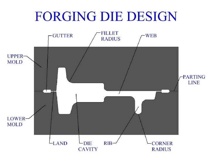
Forging Defects Ø Thin portions of a metal forging are called ribs and webs. q A rib is a section that runs perpendicular to the forging plane as determined by the parting line. § Long narrow ribs are harder to fill and require more forces, increasing the width of a long rib will better facilitate the filling of the rib with material during the process. q A web is a portion of the metal forging that runs parallel to the forging plane. § When designing a forging die, web thickness should not be too small or else there may be trouble completely filling the web with metal. § Webs that are too thin may also cool faster than the rest of the metal forging, the resulting shrinkage could cause tears or warping of the part
Forging Defects Ø Webs - Thin section parallel to parting line. Ø Ribs - thin section perpendicular to parting line Ø Gutter - area for containing flash q Dies are normally made from tool steel with high impact strength and high wear resistance.
Forging Defects • Forging Defects: 1. Surface cracking. 2. Laps formed by web buckling during forging, web thickness [material in the web area] should be increased to avoid this problem [Laps in a metal forging are caused by a buckling of the part, laps can be a result of too little material in the work piece]. 3. Internal cracks caused by oversized billet.
Forging Defects q In addition to surface cracking. Several defects in forging can be caused by the material flow patterns in the die cavity. 1. Insufficient volume of material. Material in the web of a forging can buckle during forging and develops lap [Laps formed by web buckling during forging, web thickness should be increased to avoid this problem].
Forging Defects 2. If the web is too thick, the excess material flows past the already forged portions and develops internal cracks q The previous two defects (1 &2) indicates the importance of probably controlling the volume of the blank and its flow in the cavity.
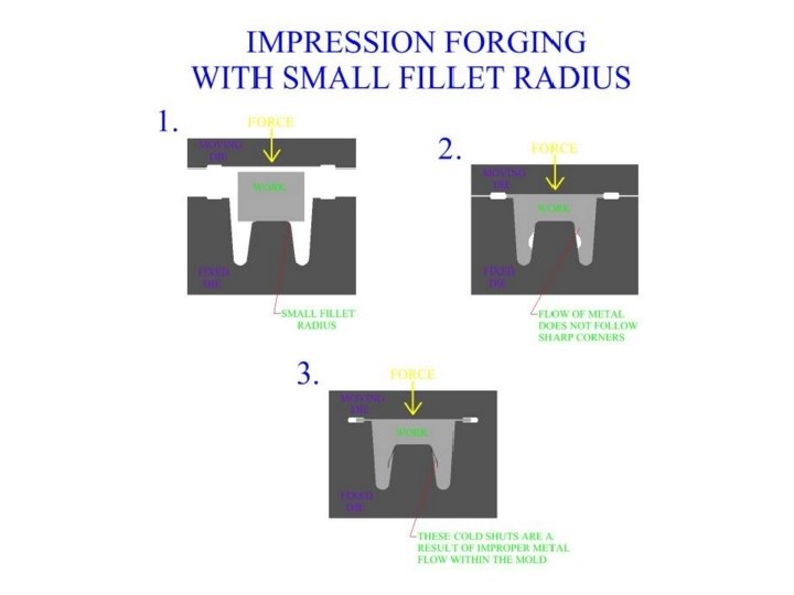
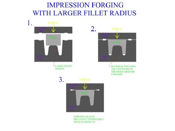
Forging Defects 3. The die radii also can significantly affect formation of defects. q The material flows better around a large corner sides that it dose around small radius. q As the work material fills the die cavity, the flow of metal will have to change directions depending upon the part's geometry. q Smooth, large filleted turns will allow the metal flow to change directions while adhering to the die's dimensions. q If corners within the metal forging are too sharp then the material may not completely follow the path of those corners, resulting in vacancies, laps, or cold shuts. Sharp corners will also act as stress raisers within the die cavity. q Good forging die design should provide adequate enough fillet and corner radius to allow for easy metal flow
Forging Defects 3. The die radii also can significantly affect formation of defects. q With smaller radii, the material can thus fold over itself, producing a lap ( cold shut : which metal does not flow properly into the corner as a result of that small cracks appear at the corners of the forged part). q Cold shuts occur when metal flows of different temperatures meet, they do not combine smoothly, a boundary layer, (cold shut), forms at their intersection. Cold shuts indicate that there is a problem with metal flow in the mold as the part is being formed
Forging Defects q. Such a defect can lead to fatigue failure and other problems during the service life of the forged component. q. So it is important to inspect the forging part prior to being placed into service, particularly for critical applications.
Forging Defects q. In general, defects in parts manufactured by metal forging can be controlled first by careful consideration of work stock volume, and by good design of the forging die, (mold). q. The main principle is to enact the right material distributions, and the right material flow to accomplish these distributions.
Forging Defects q The effect of die radii in developing defects in the forged parts
Forging Defects 4. Another important factor is the grain-flow pattern. q The grain flow lines may reaches a surface perpendicularly, exposing the grain boundaries directly to environment (knowing as end grains). q In service, they can be attacked by the environment ( such as salt water, acid rain, or other chemically active environments), thus developing rough surfaces which act as stress raiser. q End grains can be avoided: 1. by proper selection of blank orientation in the die cavity and 2. by control of material flow during forging.
Forging Defects • Reasons: 1. Insufficient volume of material to fill the die cavity completely: laps will be developed. 2. If the web is too thick: internal cracks can be developed. 3. Temperature gradients throughout the work piece during forging (Non uniform deformation of the material in the die cavity). q Forging Defects can cause fatigue failures, and wear.
Forging Defects Examples of defects in forged parts. (a) Labs formed by web buckling during forging; material should be enough to avoid this problem. (b) Internal defects caused by oversized billet; die cavities are filled prematurely. Internal cracks will be formed in the rib region.
Forging Process Design • In modern manufacturing industry, metal parts of complex geometry are often forged completely with the need for only minor finishing operations. • These parts can not be manufactured with a single forging. The work stock is taken through a series of metal forging operations that, in steps, alter the geometric shape of the material until the final process creates the desired forging. • In these types of design sequences each operation must be planned in such a way as to prepare the work piece for the next forging process. Together the series of metal forging operations that are required to create a part, make a larger single process and each individual forging operation has its place within the larger process.
Forging Process Design • When designing a complex metal forging process, great consideration should be taken with each step and how it relates to the final product. • Also, design the chosen path for the redistribution of the work material from the start of the process to the end of the last step, concentrating on smooth metal flow
Forging Process Design • Forging design, in general, should first accomplish a redistribution of the material, then the more detailed impression die forging operations, and finally finishing operations. • In addition to providing a smooth transition of material the forging processes, as a whole, should be designed to produce a controlled grain structure in the final product. • When choosing a path for material redistribution, a metal forging design should consider how this particular method of metal deformation will effect and change the grain structure of the part. • It is desirable that the final product contain a favorable grain orientation throughout the structure of its material. Such a grain structure should strengthen the part, particularly with respect to that part's application
Forging Process Design
Forging Process Design • Open die forging often plays a roll in the early stages, providing a general mass redistribution of the work metal. • Before the more detailed impression forgings can shape the work, metal must be formed in such a way as to place higher concentrations of material in regions that will require more material. • Fullering and edging of the metal, discussed in the open die forging section, are very important open die forging processes used to accomplish a rough transfer of material. • Fullering and edging will squeeze more metal into some areas of the work, while causing other areas to have less depending on the needs of the process.
Forging Process Design q. Figure shows two rough forms, one was subject to fullering the other to edging, the nature of the different processes should be apparent
Forging Process Design
Design Considerations 1. Die design: q The design of forging dies and die material selection require knowledge of 1. The strength and ductility of the workpiece material 2. Workpiece material sensitivity to strain rate and temperature 3. Its frictional characteristics 4. Forging temperature
Design Considerations q The terminology used in die design is as follow: 1. The bar is first performed (intermediate shape) by techniques such as fullering and edging. 2. Forged into the final shape 3. Finally the forged part is trimmed. q The reason for performing is recognizing that for long die life, wear is to be minimized
Design Considerations
Design Considerations q Some general rules of die design include the following: a) The parting line : is where the two dies meet. For simple shapes, the parting line is a straight line at the center of the forging; for more complex shapes, the line may be offset and may not be in a single plane. Ø The selection of the proper location for the parting line is based on: a. The shape of the part, b. Flow of the metal, c. Balance of the forces, d. And the flash
Design Considerations The parting line q. Location of the parting line is of primary importance in metal forging die design. The parting line, which defines the forging plane of the operation, is a large determinant in how metal flows through the die during the forging's compression. q. The parting line dictates where flash will be formed, and effects the grain structure of the manufactured part. It is easier to fill sections closer to the parting line than further away.
q Figure shows a metal forging with three possible locations for a parting line. The location of the parting line of C will better facilitate the flow of metal through the die cavity. q Unlike A or B, location C makes use of the maximum periphery of the forging. It is easier to fill material near the forging plane than in the further recesses of the die cavity. In addition to being a major factor in the flow of metal during the forging process, the location of the parting line is also critical in the formation of the grain structure of the forged work. The parting line acts to disrupt the metal's grain. [structure microstructural variations].
Design Considerations q Some general rules of die design include the following: b) The flash: the flash is allowed to flow into gutter. Ø A general guideline for flash clearance (between the dies) is 3% of the maximum thickness of forging. Ø The length of the land is usually five times that of the flash clearance
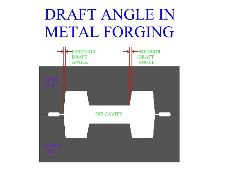
Design Considerations c) - Draft angles q. Draft angle, in metal manufacturing processes, is the taper around the internal and external sides of a part. q. Draft angle is necessary to include in the forging die design in order to allow the removal of the work from the die after the part has been forged. q. The larger the draft angle, the better it will facilitate the metal forging's removal. q. As the metal forging cools, it shrinks away from the outer surfaces of the die cavity, therefore exterior draft angles are usually made smaller than interior angles.
Design Considerations q Some general rules of die design include the following: c) Draft angles: are necessary in almost all forgings to facilitate removal of the part from die. Ø Draft angles usually range between 0. 052 (2. 90 )and 0. 174 rad (9. 90 ). Ø Because the forging shrinks in its radial direction as it cools, internal draft angles are made larger than external ones. Ø Internal angles are about (0. 1222 to 0. 1745 rad) Ø External angles are about (0. 052 to 0. 087)
Design Considerations q Some general rules of die design include the following: d) Die radii: the proper selection of die radii for corners and fillets ensures smooth flow of the metal in the die cavity and improves the die life. Ø Small radii are generally not desirable because of their adverse effect on metal flow and their tendency to wear rapidly from stress concentration and thermal cycling
Design Considerations 2. Die materials: q Because most forgings, particularly large ones, are performed at elevated temperature, die materials must have 1. High strength toughness and hardness at elevated temperature 2. Hardenability and ability to harden uniformly, 3. Resistance to mechanical and thermal shock 4. Resistance to wear ( particularly to abrasive wear because of the presence of scale on heated forging)
Design Considerations 2. Die materials: q Selection of die materials depend on: 1. The properties of workpiece 2. Complexity of workpiece shape, 3. Forging temperature, 4. Cost of die material 5. The number of forging required 6. Heat transfer characteristics of die material q Common die materials are steel containing chromium, nickel, molybdenum, and vanadium
Die Failures Die failure results from: q. Improper design q. Defective material q. Improper heat treatment and finishing operations q. Overheating (cracking caused by temperature cycling) q. Overloading-Excessive wear
Forging Advantages 1. Directional Strength • By mechanically deforming the heated metal under tightly controlled conditions, forging produces predictable uniform grain size and flow characteristics. • These qualities translate into superior metallurgical and mechanical qualities, and deliver increased directional strength in the final part.
Forging Advantages 2. Structural Strength • Forging also provides a degree of structural integrity that is unmatched by other metalworking processes. • Forging stock is also typically pre-worked to refine the structure of the ingot and remove defects or porosity. • Forging eliminates internal voids and gas pockets that can weaken metal parts. By dispersing segregation of alloys or nonmetallics. • Forging provides predictable structural integrity reduces part inspection requirements, and ensures optimum part performance under field-load conditions.
Forging Advantages 3. Impact Strength • Proper orientation of grain flow assures maximum impact strength and fatigue resistance. .
Advantages of forging • Some common advantages of forging are given as under: 1. Forging refines the structure of the metal. 2. It results in considerable saving in time, labor and material as compared to the production of similar item by cutting from a solid stock and then shaping it. 3. Forging increases the strength by setting the direction of grains. 4. Because of intense working, flaws are rarely found, so it has good reliability. 5. The reasonable degree of accuracy may be obtained in forging operation. 6. The forged part can be easily welded.
disadvantages of forging Ø Few disadvantages of forging are given as under: 1. Rapid oxidation in forging of metal surface at high temperature results in scaling which wear the dies. 2. The close tolerances in forging operations are difficult to maintain (Open-die forging is not a net-shape process and will require a subsequent machining to dimension). 3. Some materials are not readily worked by forging. 4. The initial cost of forging dies and the cost of their maintenance is high. 5. The metal get cracked or distort if worked below a specified temperature limit.
Unit Cost in Forging
Forces in forging-with no friction q If friction at the workpiece-die interfaces is zero and the material is perfectly plastic with a yield stress Y. the force at any height h, is q Where A 1 is the final cross-sectional area and is obtained from volume constancy: q If the material is strain hardening, with a true-stress-true strain curve given by the expression: q Then the forging force at any stage during plastic deformation becomes:
Shape factor • The actual forging force is greater than the ideal case. • The shape factor is to cover the effect of barreling and the friction effect. • Open-die forging is not a net -shape process and will require a subsequent machining to dimension.
Forging Force-with friction • The forging force (F) in an open-die forging operation on a solid cylindrical piece can be estimated from: • Yf = the flow stress of the material: the stress required to continue plastic deformation of the workpiece at a particular true strain. • Yf = K ϵ 1 n , n: strain hardening exponent , k: is the stress (strength) coefficient • ϵ 1 = ho= starting height; and h = height at some point during compression = the coefficient of friction r = the final radius of the workpiece h = The final height of the workpiece 128
Forging - Analysis Force required: Where: F: force A: cross-sectional area Kf: forging shaping factor Ideal Actual Yf : flow stress of the material (true stress (σ) required to keep metal ‘flowing’) Impression Die Forging Where: m: coefficient of friction D: work-part diameter (or other dimension representing contact length with die surface) h: work-part height Kf Simple w/ flash 6. 0 Complex w/ flash 8. 0 Very complex w/ flash 10. 0 Flashless (Closed Die) Coining 6. 0 Complex shape 8. 0
Hot Forging - Analysis • Theoretically, a metal in hot working behaves like a perfectly plastic material, with strain hardening exponent n = 0. – However, an additional phenomenon occurs during deformation, especially at elevated temperatures: (strain rate becomes important). Strain rate is defined: Where: V = deformation velocity. h = instantaneous height of workpiece being deformed. – As strain rate increases, resistance to deformation increases. – This effect is known as strain‑rate sensitivity. where C = strength constant m = strain‑rate sensitivity exponent
Hot Forging - Analysis the deformation force is: the work is: assume constant strain rate: the power consumed is: Where: V is the volume of the work piece t is the time
Example • A solid cylindrical slug made of 304 stainless steel is 150 mm (6 in. ) in diameter and 100 mm (4 in. ) high. It is reduced in height by 50% at room temperature, by open-die forging with flat dies. Assuming that the coefficient of friction is 0. 2, calculate the forging force at the end of the stroke. 132
Example • Forging force • The final height is hf = 100/2 = 50 mm • The final radius therefore, r = 106 mm • Determine Yf 133
True Stress (psi X 103 ) True Stress-True Strain Curves Figure 2. 6 True stresstrue strain curves in tension at room temperature for various metals. The curves start at a finite level of stress: The elastic regions have too steep a slope to be shown in this figure, and so each curve starts at the yield stress, Y, of the material. 134
Example • The absolute value of the true strain: • At a true strain of 0. 69, the true stress is about 1, 000 MPa • Thus, the forging force 135