ARM Introduction Instruction Set Architecture Aleksandar Milenkovic Email


- Slides: 31
ARM Introduction & Instruction Set Architecture Aleksandar Milenkovic E-mail: Web: milenka@ece. uah. edu http: //www. ece. uah. edu/~milenka
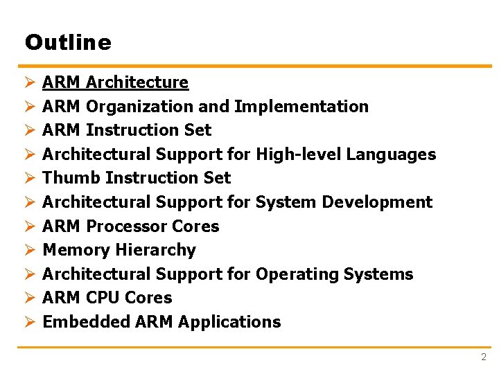
Outline Ø Ø Ø ARM Architecture ARM Organization and Implementation ARM Instruction Set Architectural Support for High-level Languages Thumb Instruction Set Architectural Support for System Development ARM Processor Cores Memory Hierarchy Architectural Support for Operating Systems ARM CPU Cores Embedded ARM Applications 2
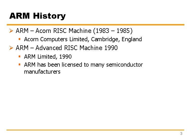
ARM History Ø ARM – Acorn RISC Machine (1983 – 1985) § Acorn Computers Limited, Cambridge, England Ø ARM – Advanced RISC Machine 1990 § ARM Limited, 1990 § ARM has been licensed to many semiconductor manufacturers 3
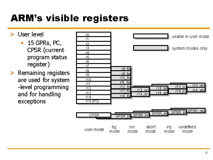
ARM’s visible registers Ø User level § 15 GPRs, PC, CPSR (current program status register) Ø Remaining registers are used for system -level programming and for handling exceptions r 0 r 1 r 2 r 3 r 4 r 5 r 6 r 7 r 8 r 9 r 10 r 11 r 12 r 13 r 14 r 15 (PC) CPSR user mode usable in user mode system modes only r 8_fiq r 9_fiq r 10_fiq r 11_fiq r 12_fiq r 13_fiq r 14_fiq r 13_svc r 14_svc r 13_abt r 14_abt r 13_irq r 14_irq r 13_und r 14_und SPSR_irq SPSR_und SPSR_abt SPSR_fiq SPSR_svc fiq mode svc mode abort mode irq mode undefined mode 4
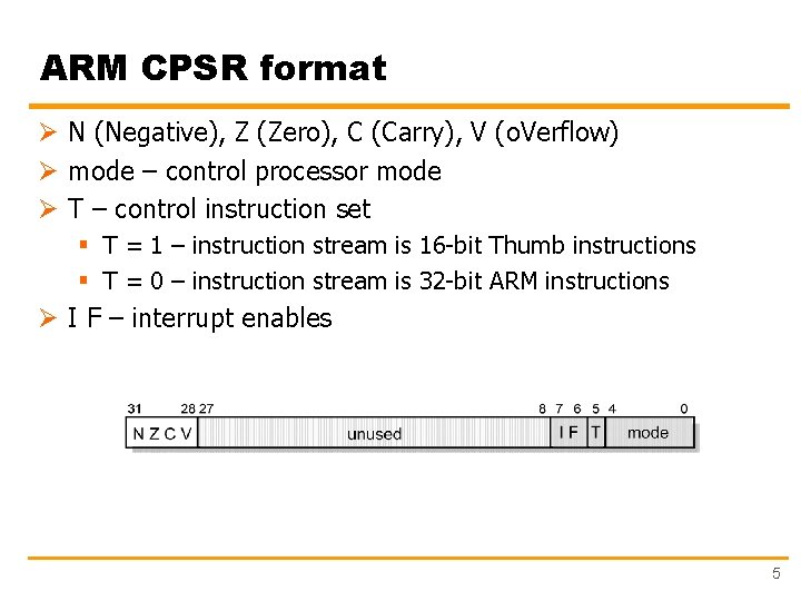
ARM CPSR format Ø N (Negative), Z (Zero), C (Carry), V (o. Verflow) Ø mode – control processor mode Ø T – control instruction set § T = 1 – instruction stream is 16 -bit Thumb instructions § T = 0 – instruction stream is 32 -bit ARM instructions Ø I F – interrupt enables 5
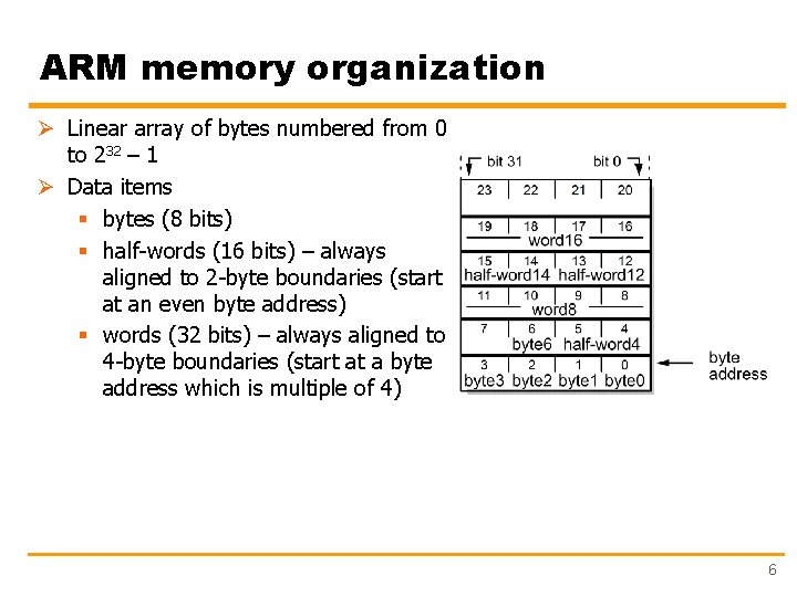
ARM memory organization Ø Linear array of bytes numbered from 0 to 232 – 1 Ø Data items § bytes (8 bits) § half-words (16 bits) – always aligned to 2 -byte boundaries (start at an even byte address) § words (32 bits) – always aligned to 4 -byte boundaries (start at a byte address which is multiple of 4) 6
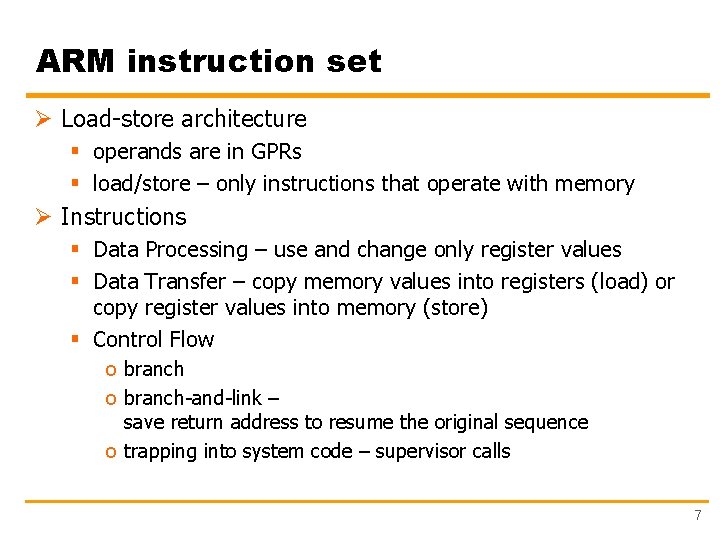
ARM instruction set Ø Load-store architecture § operands are in GPRs § load/store – only instructions that operate with memory Ø Instructions § Data Processing – use and change only register values § Data Transfer – copy memory values into registers (load) or copy register values into memory (store) § Control Flow o branch-and-link – save return address to resume the original sequence o trapping into system code – supervisor calls 7
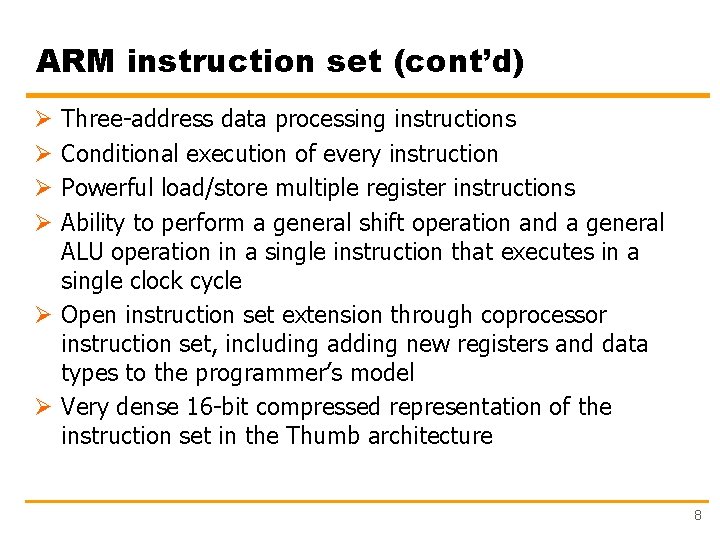
ARM instruction set (cont’d) Three-address data processing instructions Conditional execution of every instruction Powerful load/store multiple register instructions Ability to perform a general shift operation and a general ALU operation in a single instruction that executes in a single clock cycle Ø Open instruction set extension through coprocessor instruction set, including adding new registers and data types to the programmer’s model Ø Very dense 16 -bit compressed representation of the instruction set in the Thumb architecture Ø Ø 8
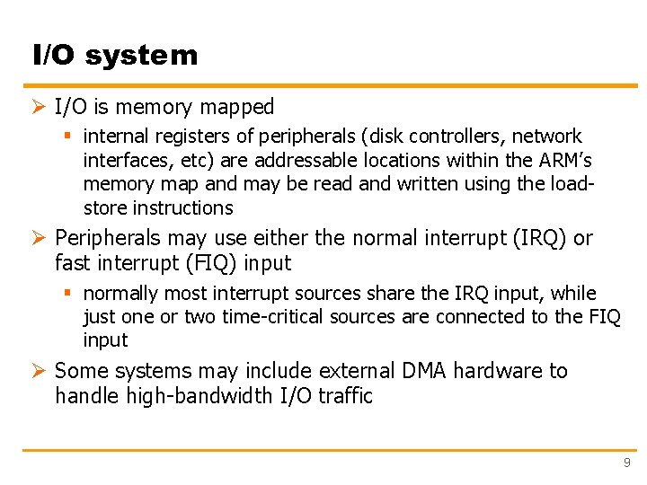
I/O system Ø I/O is memory mapped § internal registers of peripherals (disk controllers, network interfaces, etc) are addressable locations within the ARM’s memory map and may be read and written using the loadstore instructions Ø Peripherals may use either the normal interrupt (IRQ) or fast interrupt (FIQ) input § normally most interrupt sources share the IRQ input, while just one or two time-critical sources are connected to the FIQ input Ø Some systems may include external DMA hardware to handle high-bandwidth I/O traffic 9
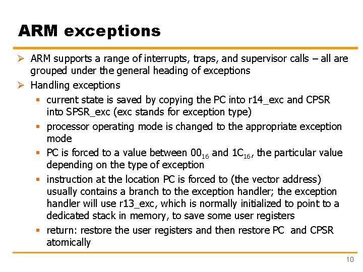
ARM exceptions Ø ARM supports a range of interrupts, traps, and supervisor calls – all are grouped under the general heading of exceptions Ø Handling exceptions § current state is saved by copying the PC into r 14_exc and CPSR into SPSR_exc (exc stands for exception type) § processor operating mode is changed to the appropriate exception mode § PC is forced to a value between 0016 and 1 C 16, the particular value depending on the type of exception § instruction at the location PC is forced to (the vector address) usually contains a branch to the exception handler; the exception handler will use r 13_exc, which is normally initialized to point to a dedicated stack in memory, to save some user registers § return: restore the user registers and then restore PC and CPSR atomically 10
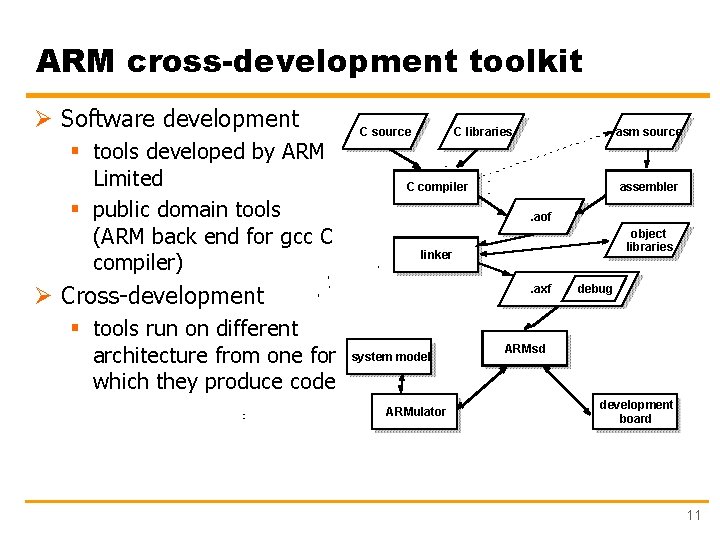
ARM cross-development toolkit Ø Software development § tools developed by ARM Limited § public domain tools (ARM back end for gcc C compiler) C source C libraries C compiler assembler. aof object libraries linker Ø Cross-development § tools run on different architecture from one for which they produce code asm source . axf system model ARMulator debug ARMsd development board 11
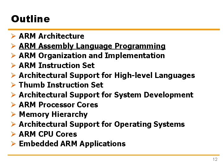
Outline Ø Ø Ø ARM Architecture ARM Assembly Language Programming ARM Organization and Implementation ARM Instruction Set Architectural Support for High-level Languages Thumb Instruction Set Architectural Support for System Development ARM Processor Cores Memory Hierarchy Architectural Support for Operating Systems ARM CPU Cores Embedded ARM Applications 12
ARM Instruction Set Ø Data Processing Instructions Ø Data Transfer Instructions Ø Control flow Instructions 13
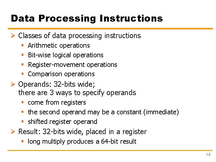
Data Processing Instructions Ø Classes of data processing instructions § § Arithmetic operations Bit-wise logical operations Register-movement operations Comparison operations Ø Operands: 32 -bits wide; there are 3 ways to specify operands § come from registers § the second operand may be a constant (immediate) § shifted register operand Ø Result: 32 -bits wide, placed in a register § long multiply produces a 64 -bit result 14
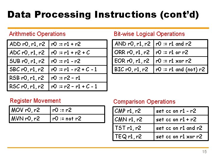
Data Processing Instructions (cont’d) Arithmetic Operations Bit-wise Logical Operations ADD r 0, r 1, r 2 r 0 : = r 1 + r 2 AND r 0, r 1, r 2 r 0 : = r 1 and r 2 ADC r 0, r 1, r 2 r 0 : = r 1 + r 2 + C ORR r 0, r 1, r 2 r 0 : = r 1 or r 2 SUB r 0, r 1, r 2 r 0 : = r 1 - r 2 EOR r 0, r 1, r 2 r 0 : = r 1 xor r 2 SBC r 0, r 1, r 2 r 0 : = r 1 - r 2 + C - 1 BIC r 0, r 1, r 2 r 0 : = r 1 and (not) r 2 RSB r 0, r 1, r 2 r 0 : = r 2 – r 1 RSC r 0, r 1, r 2 r 0 : = r 2 – r 1 + C - 1 Register Movement Comparison Operations MOV r 0, r 2 r 0 : = r 2 CMP r 1, r 2 set cc on r 1 - r 2 MVN r 0, r 2 r 0 : = not r 2 CMN r 1, r 2 set cc on r 1 + r 2 TST r 1, r 2 set cc on r 1 and r 2 TEQ r 1, r 2 set cc on r 1 xor r 2 15
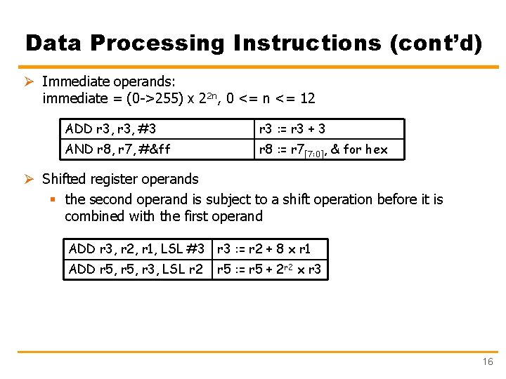
Data Processing Instructions (cont’d) Ø Immediate operands: immediate = (0 ->255) x 22 n, 0 <= n <= 12 ADD r 3, #3 r 3 : = r 3 + 3 AND r 8, r 7, #&ff r 8 : = r 7[7: 0], & for hex Ø Shifted register operands § the second operand is subject to a shift operation before it is combined with the first operand ADD r 3, r 2, r 1, LSL #3 r 3 : = r 2 + 8 x r 1 ADD r 5, r 3, LSL r 2 r 5 : = r 5 + 2 r 2 x r 3 16
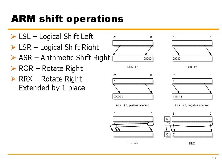
ARM shift operations Ø Ø Ø LSL – Logical Shift Left LSR – Logical Shift Right ASR – Arithmetic Shift Right ROR – Rotate Right RRX – Rotate Right Extended by 1 place 17
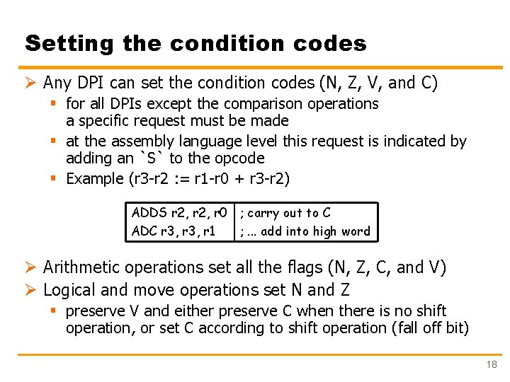
Setting the condition codes Ø Any DPI can set the condition codes (N, Z, V, and C) § for all DPIs except the comparison operations a specific request must be made § at the assembly language level this request is indicated by adding an `S` to the opcode § Example (r 3 -r 2 : = r 1 -r 0 + r 3 -r 2) ADDS r 2, r 0 ; carry out to C ADC r 3, r 1 ; . . . add into high word Ø Arithmetic operations set all the flags (N, Z, C, and V) Ø Logical and move operations set N and Z § preserve V and either preserve C when there is no shift operation, or set C according to shift operation (fall off bit) 18
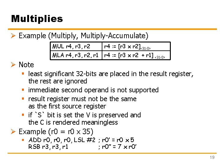
Multiplies Ø Example (Multiply, Multiply-Accumulate) MUL r 4, r 3, r 2 r 4 : = [r 3 x r 2]<31: 0> MLA r 4, r 3, r 2, r 1 r 4 : = [r 3 x r 2 + r 1] <31: 0> Ø Note § least significant 32 -bits are placed in the result register, the rest are ignored § immediate second operand is not supported § result register must not be the same as the first source register § if `S` bit is set the V is preserved and the C is rendered meaningless Ø Example (r 0 = r 0 x 35) § ADD r 0, LSL #2 ; r 0’ = r 0 x 5 RSB r 3, r 1 ; r 0’’ = 7 x r 0’ 19
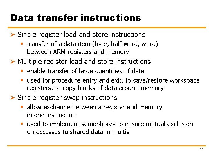
Data transfer instructions Ø Single register load and store instructions § transfer of a data item (byte, half-word, word) between ARM registers and memory Ø Multiple register load and store instructions § enable transfer of large quantities of data § used for procedure entry and exit, to save/restore workspace registers, to copy blocks of data around memory Ø Single register swap instructions § allow exchange between a register and memory in one instruction § used to implement semaphores to ensure mutual exclusion on accesses to shared data in multis 20
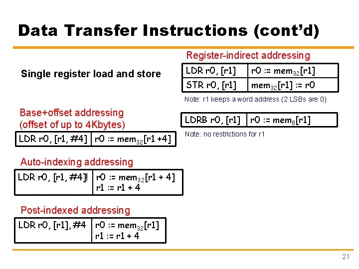
Data Transfer Instructions (cont’d) Register-indirect addressing Single register load and store LDR r 0, [r 1] r 0 : = mem 32[r 1] STR r 0, [r 1] mem 32[r 1] : = r 0 Note: r 1 keeps a word address (2 LSBs are 0) Base+offset addressing (offset of up to 4 Kbytes) LDR r 0, [r 1, #4] r 0 : = mem 32[r 1 +4] LDRB r 0, [r 1] r 0 : = mem 8[r 1] Note: no restrictions for r 1 Auto-indexing addressing LDR r 0, [r 1, #4]! r 0 : = mem 32[r 1 + 4] r 1 : = r 1 + 4 Post-indexed addressing LDR r 0, [r 1], #4 r 0 : = mem 32[r 1] r 1 : = r 1 + 4 21
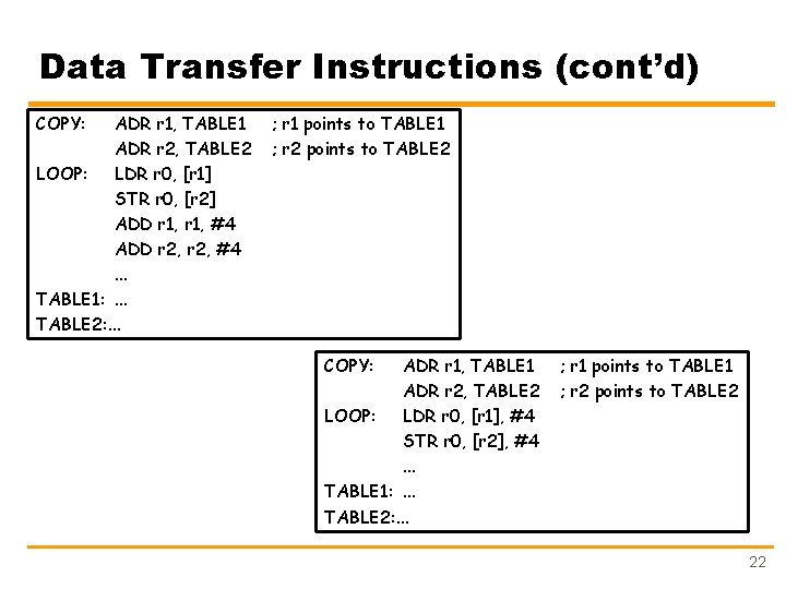
Data Transfer Instructions (cont’d) COPY: ADR r 1, TABLE 1 ADR r 2, TABLE 2 LOOP: LDR r 0, [r 1] STR r 0, [r 2] ADD r 1, #4 ADD r 2, #4. . . TABLE 1: . . . TABLE 2: . . . ; r 1 points to TABLE 1 ; r 2 points to TABLE 2 COPY: ADR r 1, TABLE 1 ADR r 2, TABLE 2 LOOP: LDR r 0, [r 1], #4 STR r 0, [r 2], #4. . . TABLE 1: . . . TABLE 2: . . . ; r 1 points to TABLE 1 ; r 2 points to TABLE 2 22
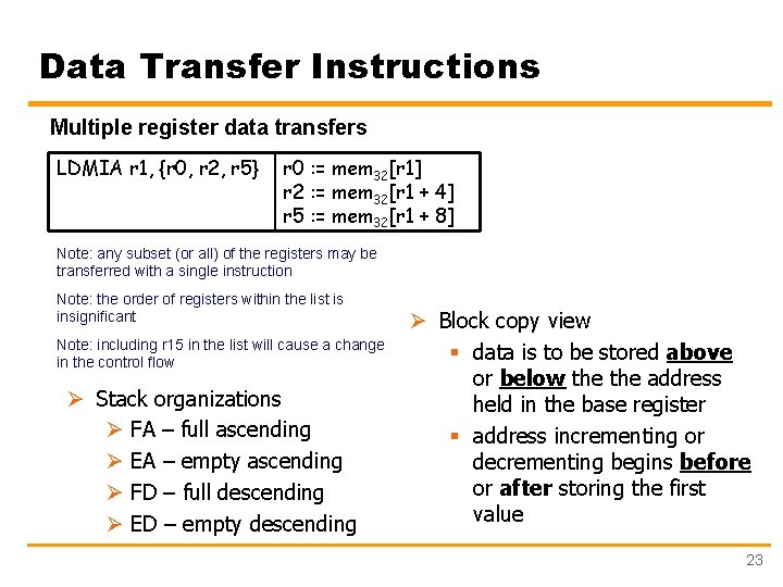
Data Transfer Instructions Multiple register data transfers LDMIA r 1, {r 0, r 2, r 5} r 0 : = mem 32[r 1] r 2 : = mem 32[r 1 + 4] r 5 : = mem 32[r 1 + 8] Note: any subset (or all) of the registers may be transferred with a single instruction Note: the order of registers within the list is insignificant Note: including r 15 in the list will cause a change in the control flow Ø Stack organizations Ø FA – full ascending Ø EA – empty ascending Ø FD – full descending Ø ED – empty descending Ø Block copy view § data is to be stored above or below the address held in the base register § address incrementing or decrementing begins before or after storing the first value 23
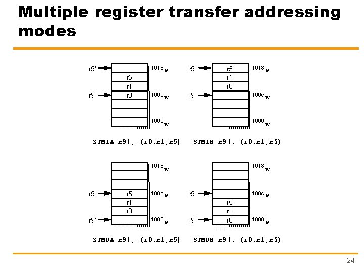
Multiple register transfer addressing modes 1018 r 9’ r 9 r 5 r 1 r 0 16 100 c 16 1000 r 9’ r 5 r 1 r 0 16 STMDA r 9!, {r 0, r 1, r 5} 1018 16 100 c 16 r 9 1000 16 STMIB r 9!, {r 0, r 1, r 5} 1018 16 100 c 16 1000 r 5 r 1 r 0 16 STMIA r 9!, {r 0, r 1, r 5} 1018 r 9’ 100 c 16 r 9’ 16 r 5 r 1 r 0 1000 16 STMDB r 9!, {r 0, r 1, r 5} 24
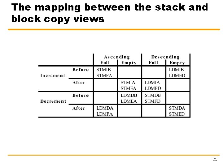
The mapping between the stack and block copy views 25
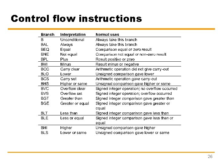
Control flow instructions 26
Conditional execution Ø Conditional execution to avoid branch instructions used to skip a small number of non-branch instructions Ø Example CMP r 0, #5 BEQ BYPASS ADD r 1, r 0 SUB r 1, r 2 BYPASS: . . . ; ; if (r 0!=5) { ; r 1: =r 1+r 0 -r 2 ; } With conditional execution CMP r 0, #5 ADDNE r 1, r 0 SUBNE r 1, r 2. . . ; ; ; Note: add 2 –letter condition after the 3 -letter opcode ; if ((a==b) && (c==d)) e++; CMP r 0, r 1 CMPEQ r 2, r 3 ADDEQ r 4, #1 27
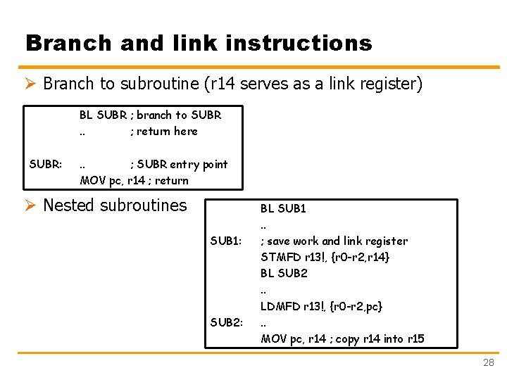
Branch and link instructions Ø Branch to subroutine (r 14 serves as a link register) BL SUBR ; branch to SUBR. . ; return here SUBR: . . ; SUBR entry point MOV pc, r 14 ; return Ø Nested subroutines SUB 1: SUB 2: BL SUB 1. . ; save work and link register STMFD r 13!, {r 0 -r 2, r 14} BL SUB 2. . LDMFD r 13!, {r 0 -r 2, pc}. . MOV pc, r 14 ; copy r 14 into r 15 28
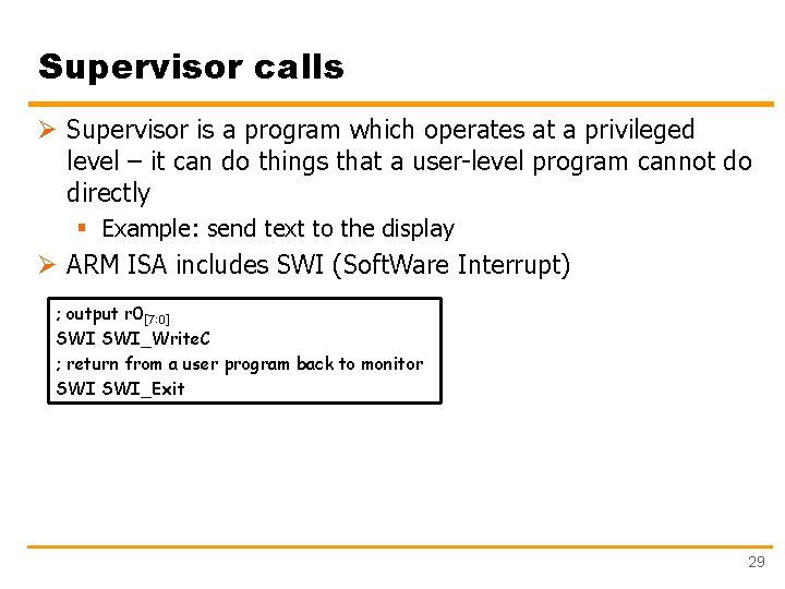
Supervisor calls Ø Supervisor is a program which operates at a privileged level – it can do things that a user-level program cannot do directly § Example: send text to the display Ø ARM ISA includes SWI (Soft. Ware Interrupt) ; output r 0[7: 0] SWI_Write. C ; return from a user program back to monitor SWI_Exit 29
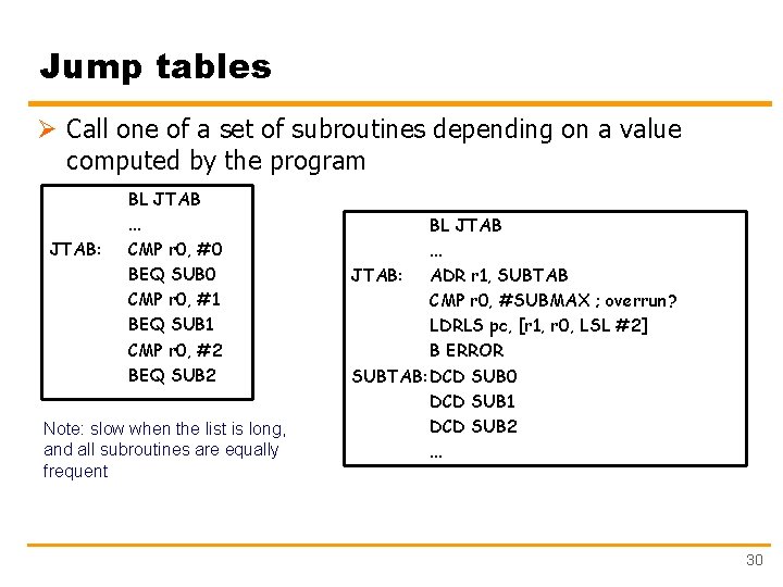
Jump tables Ø Call one of a set of subroutines depending on a value computed by the program JTAB: BL JTAB. . . CMP r 0, #0 BEQ SUB 0 CMP r 0, #1 BEQ SUB 1 CMP r 0, #2 BEQ SUB 2 Note: slow when the list is long, and all subroutines are equally frequent BL JTAB. . . JTAB: ADR r 1, SUBTAB CMP r 0, #SUBMAX ; overrun? LDRLS pc, [r 1, r 0, LSL #2] B ERROR SUBTAB: DCD SUB 0 DCD SUB 1 DCD SUB 2. . . 30
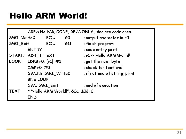
Hello ARM World! AREA Hello. W, CODE, READONLY ; declare code area SWI_Write. C EQU &0 ; output character in r 0 SWI_Exit EQU &11 ; finish program ENTRY ; code entry point START: ADR r 1, TEXT ; r 1 <- Hello ARM World! LOOP: LDRB r 0, [r 1], #1 ; get the next byte CMP r 0, #0 ; check for text end SWINE SWI_Write. C ; if not end of string, print BNE LOOP SWI_Exit ; end of execution TEXT = “Hello ARM World!”, &0 a, &0 d, 0 END 31