AIR POLLUTION CONTROL TECHNIQUES SOURCE CONTROL TECHNOLOGY Air


 � An ESP is a particle control device that uses electrical")

")

")


 � These towers are very effective in removing particles in")


- Slides: 39
AIR POLLUTION CONTROL TECHNIQUES
SOURCE CONTROL TECHNOLOGY � Air quality management sets the tools to control air pollutant emissions. � Control measurements describes the equipment, processes or actions used to reduce air pollution. � The extent of pollution reduction varies among technologies and measures. � The selection of control technologies depends on environmental, engineering, economic factors and pollutant type.
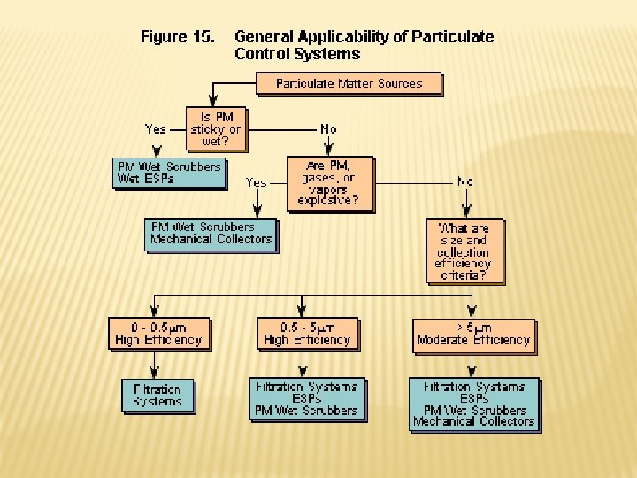
TYPES OF COLLECTION EQUIPMENTS 1. 2. 3. 4. 5. Gravity settler Cyclones Electrostatic precipitators Bag filters Wet scrubbers
SETTLING CHAMBERS � � Settling chambers use the force of gravity to remove solid particles. The gas stream enters a chamber where the velocity of the gas is reduced. Large particles drop out of the gas and are recollected in hoppers. Because settling chambers are effective in removing only larger particles, they are used in conjunction with a more efficient control device. Figure: Settling chambers
ADVANTAGES Ø Simple construction. Ø low initial cost Ø Low maintenance cost. Ø Low pressure drop. Ø Dry and continuous disposal of solid particulates DISADVANTAGES Ø Large space requirements. Ø Only comparatively large particles can be collected.
APPLICATIONS Industrial application of this equipments is limited. Ø Settling chamber are used widely for removal of large solid particulates from natural draft furnaces, kilns etc. Ø They are also sometimes used in the process industries , particularly the food and metallurgical industries, as a first step in dust control. Ø
CYCLONES � � � The general principle of inertia separation is that the particulate-laden gas is forced to change direction. As gas changes direction, the inertia of the particles causes them to continue in the original direction and be separated from the gas stream. The walls of the cyclone narrow toward the bottom of the unit, allowing the particles to be collected in a hopper. The cleaner air leaves the cyclone through the top of the chamber, flowing upward in a spiral vortex, formed within a downward moving spiral. Cyclones are efficient in removing large particles but are not as efficient with smaller particles. For this reason, they are used with other particulate control devices. Figure: Cyclone Collector
MULTI CYCLONE MECHANICAL COLLECTOR
CYCLONE
ADVANTAGES DISADVANTAGES Ø Low initial cost. Ø Low collection efficiency for particles Ø Simple construction and below 5 -10µm in operation diameter. Ø Low pressure drop Ø Equipment is to be Ø Low maintenance severe abrasive requirement deterioration. Ø It has no moving parts. Ø Decreasing collection Ø Continuous disposal of efficiency. solid particulates. Ø They can be constructed of any material as requirement.
APPLICATIONS In cement manufacture Ø Feed and grain process Ø Food and beverages process Ø Minerals process Ø Paper and textile industries Ø Wood working industries Ø
FABRIC FILTERS � Fabric filters, or bughouses, remove dust from a gas stream by passing the stream through a porous fabric. The fabric filter is efficient at removing fine particles and can exceed efficiencies of 99 percent in most applications. Figure: Fabric filter (baghouse) components
CONTI…. . � The selection of the fiber material and fabric construction is important to baghouse performance. � The fiber material from which the fabric is made must have adequate strength characteristics at the maximum gas temperature expected and adequate chemical compatibility with both the gas and the collected dust. � One disadvantage of the fabric filter is that hightemperature gases often have to be cooled before contacting the filter medium.
BAGHOUSE FILTER
BAGHOUSE FILTER
ELECTROSTATIC PRECIPITATORS (ESP) � An ESP is a particle control device that uses electrical forces to move the particles out of the flowing gas stream and onto collector plates. � The ESP places electrical charges on the particles, causing them to be attracted to oppositely charged metal plates located in the precipitator. Figure: Electrostatic precipitator components
CONTI…. � The particles are removed from the plates by "rapping" and collected in a hopper located below the unit. � The removal efficiencies for ESPs are highly variable; however, for very small particles alone, the removal efficiency is about 99%. � Electrostatic precipitators are not only used in utility applications but also other industries (for other exhaust gas particles) such as cement (dust), pulp & paper (salt cake & lime dust), petrochemicals (sulfuric acid mist), and steel (dust & fumes).
ELECTROSTATIC PRECIPITATOR (ESP)
WORKING PHENOMENA
ELECTROSTATIC PRECIPITATOR (ESP)
ADVANTAGES Ø High collection efficiency. Ø Particles as small as 0. 1µm can be removed. Ø Low maintenance and operating cost. Ø Low pressure drop. Ø Treatment time is negligible. Ø Cleaning is easy by removing units of the precipitator from operation. Ø There is no limit to solid, liquid or corrosive chemical usage. DISADVANTAGES Ø High initial cost Ø Space requirement is more. Ø Possible explosive hazardous during collection of gases. Ø Precautions are very necessary during operation. Ø The poisonous gas, ozone is produced.
TYPES OF SCRUBBERS � 1. Spray Towers � 2. Venturi Scrubbers � 3. Cyclone Scrubbers � 4. Packed Bed Scrubbers
SPRAY TOWERS � Simplest type of Wet Scrubber. � Water is applied through nozzles. � It can be circular or rectangular. � The flue gas is passed with the fluid (usually water) from nozzles. � The clean gas is collected from the top while water with the particles is collected at the hopper bottom. � It shows very less energy loss and can handle very large quantity of gases.
SPRAY TOWERS (CONTI…. ) � These towers are very effective in removing particles in excess of 10µm. � The maximum efficiency occurs if droplets have a diameter of 800µm (0. 8 mm). � The efficiency of spray tower depends upon the droplet size , flow velocity of gas, velocity of liquid. � Effectiveness varies with the particle size. � It is 94% for 5µm particles to 99%
VENTURI SCRUBBERS � � � Venturi scrubbers use a liquid stream to remove solid particles. In the venturi scrubber, gas laden with particulate matter passes through a short tube with flared ends and a constricted middle. This constriction causes the gas stream to speed up when the pressure is increased. Figure: Venturi scrubber components
CONTI…. � The difference in velocity and pressure resulting from the constriction causes the particles and water to mix and combine. � The reduced velocity at the expanded section of the throat allows the droplets of water containing the particles to drop out of the gas stream. � Venturi scrubbers are effective in removing small particles, with removal efficiencies of up to 99 percent. � One drawback of this device, however, is the production of wastewater.
CONTROL OF GASEOUS POLLUTANTS FROM STATIONARY SOURCES � � The most common method for controlling gaseous pollutants is the addition of add-on control devices to recover or destroy a pollutant. There are four commonly used control technologies for gaseous pollutants: Absorption, � Adsorption, � Condensation, and � Incineration (combustion) �
ABSORPTION � � The removal of one or more selected components from a gas mixture by absorption is probably the most important operation in the control of gaseous pollutant emissions. Absorption is a process in which a gaseous pollutant is dissolved in a liquid. Water is the most commonly used absorbent liquid. As the gas stream passes through the liquid, the liquid absorbs the gas, in much the same way that sugar is absorbed in a glass of water when stirred. Typical Packed Column Diagram
CONTI…. � Absorbers are often referred to as scrubbers, and there are various types of absorption equipment. � The principal types of gas absorption equipment include spray towers, packed columns, spray chambers, and venture scrubbers. � In general, absorbers can achieve removal efficiencies greater than 95 percent. One potential problem with absorption is the generation of waste-water, which converts an air pollution problem to a water pollution problem.
ADSORPTION � � � When a gas or vapor is brought into contact with a solid, part of it is taken up by the solid. The molecules that disappear from the gas either enter the inside of the solid, or remain on the outside attached to the surface. The former phenomenon is termed absorption and the latter adsorption. The most common industrial adsorbents are activated carbon, silica gel, and alumina, because they have enormous surface areas per unit weight. Activated carbon is the universal standard for purification and removal of trace organic contaminants from liquid and vapor streams.
� Carbon adsorption systems are either regenerative or nonregenerative. � Regenerative system usually contains more than one carbon bed. As one bed actively removes pollutants, another bed is being regenerated for future use. � Non-regenerative systems have thinner beds of activated carbon. In a non-regenerative adsorber, the spent carbon is disposed of when it becomes saturated with the pollutant. Regenerative Carbon Adsorption System Non-Regenerative Carbon Adsorption System
CONDENSATION � Condensation is the process of converting a gas or vapor to liquid. Any gas can be reduced to a liquid by lowering its temperature and/or increasing its pressure. � Condensers are typically used as pretreatment devices. They can be used ahead of absorbers, adsorbers, and incinerators to reduce the total gas volume to be treated by more expensive control equipment. � Condensers used for pollution control are contact condensers and surface condensers.
� � � In a contact condenser, the gas comes into contact with cold liquid. In a surface condenser, the gas contacts a cooled surface in which cooled liquid or gas is circulated, such as the outside of the tube. Removal efficiencies of condensers typically range from 50 percent to more than 95 percent, depending on design and applications. Contact condenser Surface condenser
INCINERATION � � Incineration, also known as combustion, is most used to control the emissions of organic compounds from process industries. This control technique refers to the rapid oxidation of a substance through the combination of oxygen with a combustible material in the presence of heat. When combustion is complete, the gaseous stream is converted to carbon dioxide and water vapor. Equipment used to control waste gases by combustion can be divided in three categories: � � � Direct combustion or flaring, Thermal incineration and Catalytic incineration.
DIRECT COMBUSTOR � � Direct combustor is a device in which air and all the combustible waste gases react at the burner. Complete combustion must occur instantaneously since there is no residence chamber. A flare can be used to control almost any emission stream containing volatile organic compounds. Studies conducted by EPA have shown that the destruction efficiency of a flare is about 98 percent.
§In thermal incinerators the combustible waste gases pass over or around a burner flame into a residence chamber where oxidation of the waste gases is completed. Thermal incinerators can destroy gaseous pollutants at efficiencies of greater than 99 percent when operated correctly. Thermal incinerator general case
ØCATALYTIC INCINERATORS Are very similar to thermal incinerators. The main difference is that after passing through the flame area, the gases pass over a catalyst bed. A catalyst promotes oxidation at lower temperatures, thereby reducing fuel costs. Destruction efficiencies greater than 95 percent are possible using a catalytic incinerator. Catalytic incinerator
REFERENCES � � � USEPA, 2007. Online literature from www. epa. gov Rao, M. N. and Rao, H. V. N. , 1993. Air Pollution, Tata Mc. Graw Hill, New Delhi. Murty, B. P. , 2004. Environmental Meteorology, I. K. International Pvt. Ltd. , New Delhi. Nevers, N. D. 2000. Air Pollution Control Engineering, Second Edition, Pub. , Mc. Graw Hill, New York. Cheremisinoff, N. P. , 2002. Handbook of Air Pollution Prevention and Control, Pub. , Butterworth-Heinemann, Elsevier Science, USA.