A Seminar On Validation of Heating Ventilation and

- Slides: 53
A Seminar On Validation of Heating, Ventilation and Air conditioning System Department of Quality Assurance Maliba Pharmacy College 1
Content � Introduction � Validation of HVAC � HVAC Qualification � Validation master plan � Design Qualification(DQ) � Installation Qualification(IQ) � Operational Qualification(OQ) � Performance Qualification(PQ) � Validation parameter � References 2
Introduction Heating Ventilation and Air Conditioning system(HVAC) HVAC systems can have an impact on product quality Ø It can provide comfortable conditions for operators Ø The impact on premises and prevention of contamination and cross-contamination to be considered at the design stage Ø Temperature, relative humidity control where appropriate Ø Supplement to basic GMP Ø 3
What is contamination? It is "the undesired introduction of impurities (chemical/ microbial/ foreign matter) into or on to starting material or intermediate – during sampling, production, packaging or repackaging“. Contaminants are : Ø Ø Ø Products or substances other than the product being manufactured Foreign matter Particulate matter Micro-organisms Endotoxins (degraded micro-organisms) 4
What is cross-contamination? “Contamination of a starting material, intermediate product, or finished product with another starting material or product during production”. Cross-contamination originates from: Ø Ø Poorly designed air handling systems and dust extraction systems Poorly operated and maintained air handling systems and dust extraction systems Inadequate procedures for personnel and equipment Insufficiently cleaned equipment 5
Cross-contamination can be minimized by: Ø Personnel procedures Ø Adequate premises Ø Use of closed production systems Ø Adequate, validated cleaning procedures Ø Appropriate levels of protection of product Ø Correct air pressure cascade 6
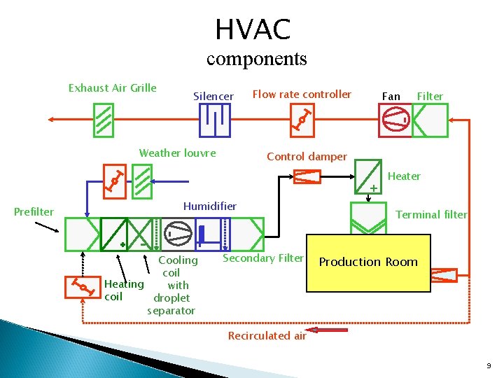
HVACsystem consists of: Ø Ø Ø Air conditioner AHUs Dehumidifier / Heater Filters (Pre & HEPA) Dust Extractors Ducting (For delivery of controlled air) Supply Fans Smoke Detector Dampers Humidity / Temperature / Pressure sensors Bag Filters Heating / Cooling Coils 7
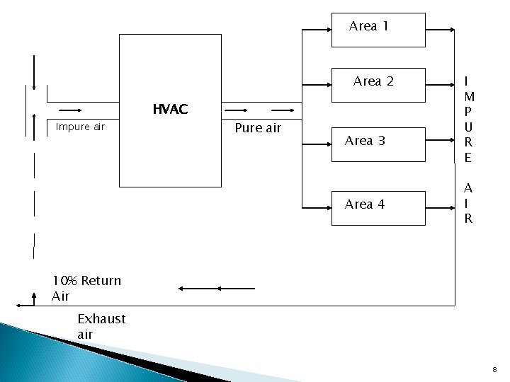
Area 1 Area 2 Impure air HVAC Pure air Area 3 Area 4 I M P U R E A I R 10% Return Air Exhaust air 8
HVAC components Exhaust Air Grille Silencer Weather louvre Flow rate controller Fan Control damper + Prefilter Humidifier Cooling coil Heating with coil droplet separator Filter Secondary Filter Heater Terminal filter Production Room Recirculated air 9
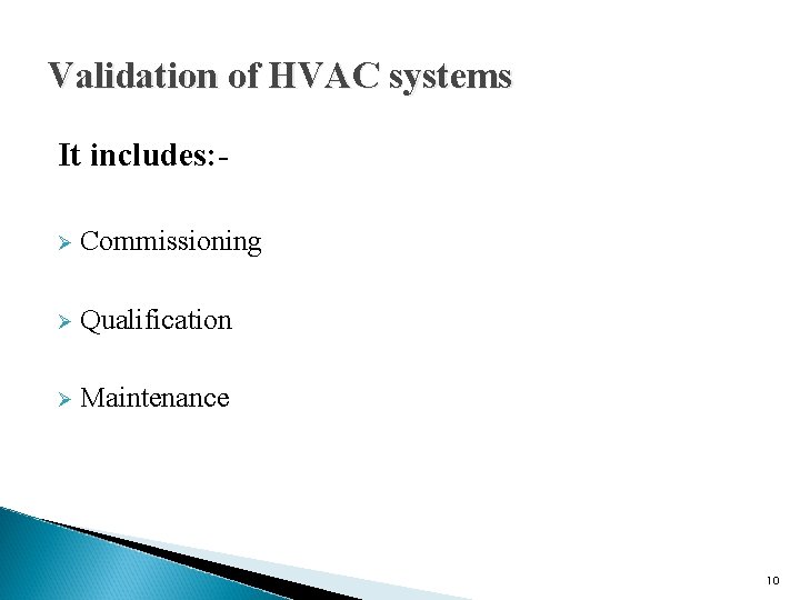
Validation of HVAC systems It includes: Ø Commissioning Ø Qualification Ø Maintenance 10
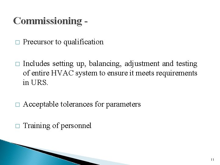
Commissioning � Precursor to qualification � Includes setting up, balancing, adjustment and testing of entire HVAC system to ensure it meets requirements in URS. � Acceptable tolerances for parameters � Training of personnel 11
Conti… Records and data maintained include: � Installation records – documented evidence of measure capacities of the system � Data: design and measurement for, e. g. air flow, system pressures � O&M manuals, schematic drawings, protocols, reports 12
Qualification Ø To ensure that equipment is designed as per requirement, installed properly. Ø Action of proving that any equipment works correctly and leads to the expected results. 13
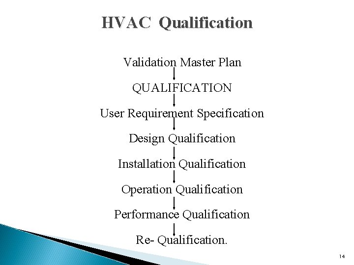
HVAC Qualification Validation Master Plan QUALIFICATION User Requirement Specification Design Qualification Installation Qualification Operation Qualification Performance Qualification Re- Qualification. 14
Conti… Ø Manufacturers should qualify HVAC systems using a riskbased approach. Ø The qualification of the HVAC system should be described in a validation master plan (VMP). Ø The validation master plan should define the nature and extent of testing and the test procedures and protocols to be followed. Ø A change control procedure should be followed 15
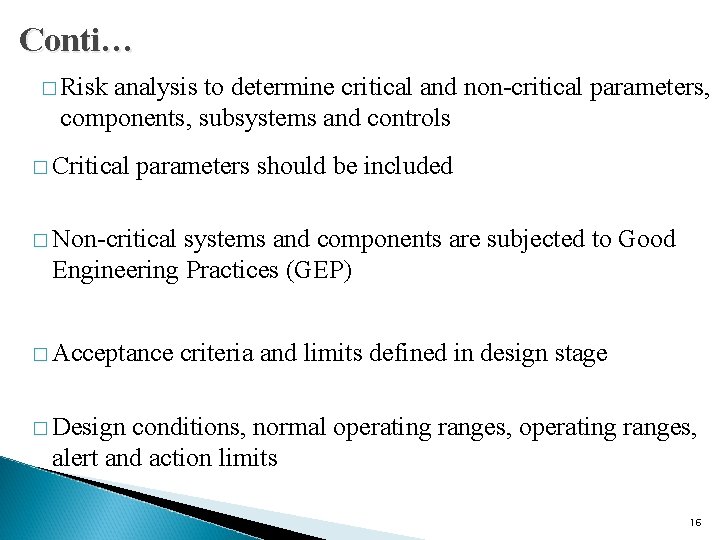
Conti… � Risk analysis to determine critical and non-critical parameters, components, subsystems and controls � Critical parameters should be included � Non-critical systems and components are subjected to Good Engineering Practices (GEP) � Acceptance criteria and limits defined in design stage � Design conditions, normal operating ranges, alert and action limits 16
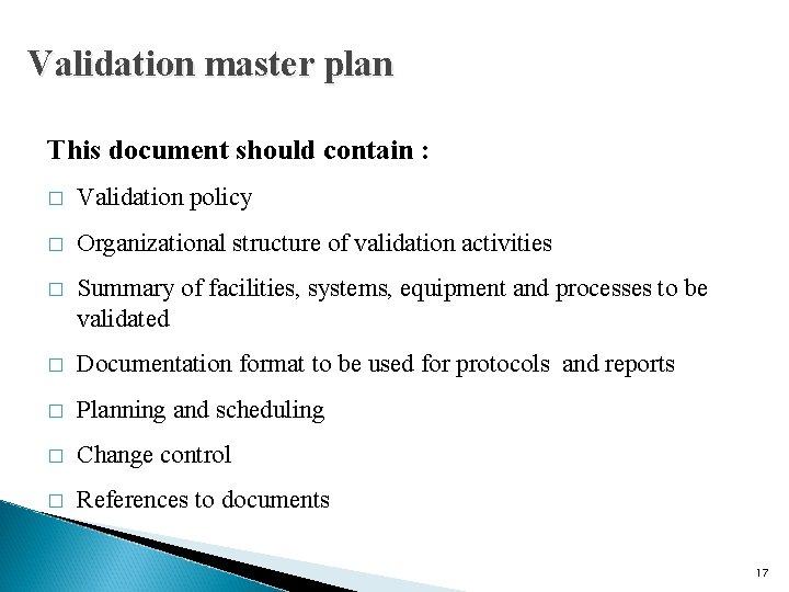
Validation master plan This document should contain : � Validation policy � Organizational structure of validation activities � Summary of facilities, systems, equipment and processes to be validated � Documentation format to be used for protocols and reports � Planning and scheduling � Change control � References to documents 17
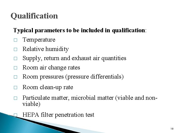
Qualification Typical parameters to be included in qualification: � Temperature Relative humidity Supply, return and exhaust air quantities Room air change rates Room pressures (pressure differentials) � Room clean-up rate � Particulate matter, microbial matter (viable and nonviable) � HEPA filter penetration test � � 18
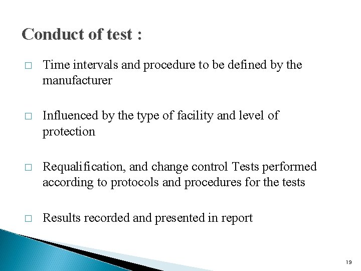
Conduct of test : � Time intervals and procedure to be defined by the manufacturer � Influenced by the type of facility and level of protection � Requalification, and change control Tests performed according to protocols and procedures for the tests � Results recorded and presented in report 19
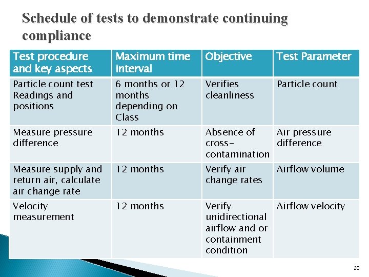
Schedule of tests to demonstrate continuing compliance Test procedure and key aspects Maximum time interval Objective Test Parameter Particle count test Readings and positions 6 months or 12 months depending on Class Verifies cleanliness Particle count Measure pressure difference 12 months Absence of Air pressure crossdifference contamination Measure supply and return air, calculate air change rate 12 months Verify air change rates Velocity measurement 12 months Verify Airflow velocity unidirectional airflow and or containment condition Airflow volume 20
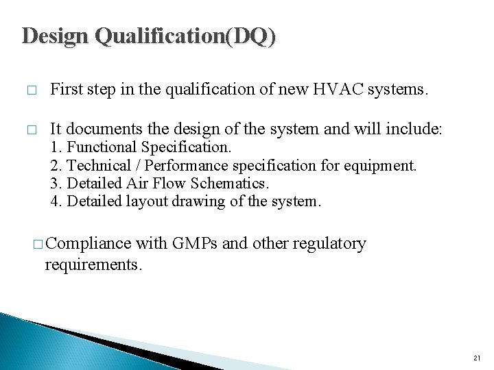
Design Qualification(DQ) � First step in the qualification of new HVAC systems. � It documents the design of the system and will include: 1. Functional Specification. 2. Technical / Performance specification for equipment. 3. Detailed Air Flow Schematics. 4. Detailed layout drawing of the system. � Compliance with GMPs and other regulatory requirements. 21
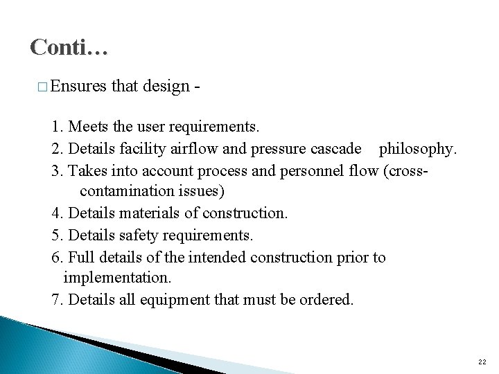
Conti… � Ensures that design - 1. Meets the user requirements. 2. Details facility airflow and pressure cascade philosophy. 3. Takes into account process and personnel flow (crosscontamination issues) 4. Details materials of construction. 5. Details safety requirements. 6. Full details of the intended construction prior to implementation. 7. Details all equipment that must be ordered. 22
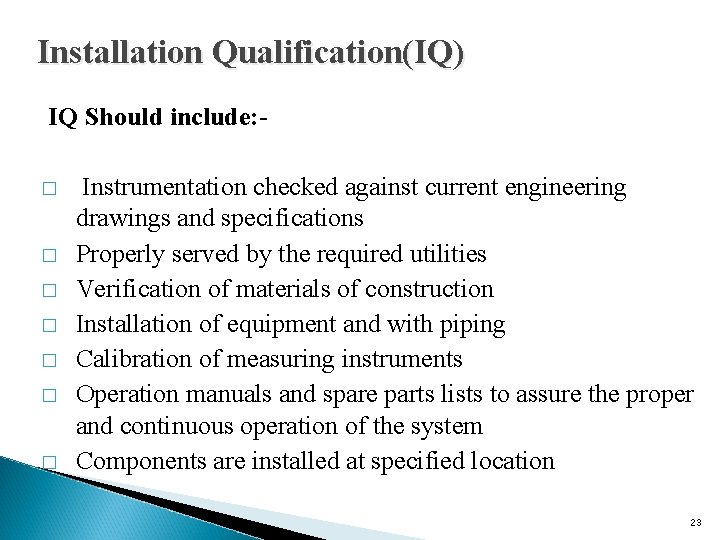
Installation Qualification(IQ) IQ Should include: � � � � Instrumentation checked against current engineering drawings and specifications Properly served by the required utilities Verification of materials of construction Installation of equipment and with piping Calibration of measuring instruments Operation manuals and spare parts lists to assure the proper and continuous operation of the system Components are installed at specified location 23
Conti…. IQ Document should containØ Ø Instrument name, model, I. D. No. , Personnel responsible for activities and Date. A fully verified installation that complies with the documented design. (all deviations will have been recorded and assessed. ) All equipment documentation and maintenance requirements would be documented. Completed calibration of measuring instruments. 24
Conti…. � Calibration verification: To provide a list of critical instrumentation and control panel and to document that they have been identified and calibrated in accordance with the approved procedure � SOP verification : To verify that required SOPs exist in either draft or final form and must be current and approved for use. � Utilities Connection Verification: Utilities supported to HVAC need to be verified to assure that they are installed properly. 25
Conti…. � Change Parts and Replacement Parts Verification � Maintenance � Critical Procedures Verification Systems Change Request Procedure verification � Lubricants Verification 26
Operation Qualification � The purpose of OQ is to establish, through documented testing, that all critical components are capable of operating within established limits and tolerances. � The purpose of OQ is to verify and document that an HVAC system provides acceptable operational control under “at-rest” conditions. � Scope of OQ is to test the individual components of the system such as AHU, blowers and others. 27
Conti… Operation Qualification Checks � Ability to provide air of sufficient quality and quantity to ensure achievement of specified clean room conditions. � Ability to maintain temperature, relative humidity and pressure set points. � Ability to maintain any critical parameters stated in the DQ consistently. 28
Conti…. � Includes the tests that have been developed from knowledge of processes, systems and equipment. � Tests to include a condition or a set of conditions encompassing upper and lower operating limits, sometimes referred to as ‘worst case’ conditions. 29
OQ also includes: � Testing � Equipment Calibration Verification Instrumentation Calibration verification � SOP Verification � Operation Qualification tests 30
Conti… OQ protocols to be written and approved prior to completion. It includes following: � All relevant SOPs should be in place � Temperature measurement report � Humidity measurement report � Differential pressure measurement report � Air flow direction measurement report � Room particle count measurement report � All maintenance/ cleaning instructions available � All O & M staff to be trained to use and maintain the system. � Sign off. (Compliance Certificate by Engineering Dept & QA) 31
Performance Qualification � The purpose of PQ is to verify and document that an HVAC system provides acceptable control under ‘ Full Operational ‘ conditions. � PQ should follow successful completion of IQ and OQ. � PQ verifies that the critical parameters, as defined in the DQ are being achieved. 32
Conti… PQ Should include � Test to include a condition or set of conditions encompassing upper and lower operating limits. � Tests should be conducted under “in use”, condition either or simulated as close as possible to the actual process 33
Conti… � PQ is used to demonstrate consistent achievement of critical parameters over time. ( under manufacturing conditions) � PQ and OQ tests are sometimes performed in conjunction with one another. � Any changes to the HVAC system should be revalidated before proceeding to the PQ phase. 34
Validation Parameters � Air flow measurement � Room air changes per hour. � Filter Integrity Testing (HEPA Leak test) � Pressure Differentials � Particulate count measurement � Recovery test � Temperature and Relative Humidity � Air Flow Pattern � Microbial Count 35
Conti… A. PHYSICAL TESTS A 1. NON-VIABLE PARTICLE COUNTS � Equipment �Optical Particle Counter (Discrete Particle Counter) �Air sample is drawn into the instrument & passed through light scattering device. The signal that this generates is electronically processed to display particle counts at different size ranges. � Sample Volume � 1 cubic ft � Sample Time � 1 Min 36
Conti… � Frequency: GMP compliance: - Quarterly Sch M - 6 Monthly �Acceptance criteria: 1. Critical environments: The particle concentration under the dynamic condition should not more than 100 particle of 0. 5µm and larger per cubic meter (for class 100 area) 37
Conti… A 2. PRESSURE DIFFERENTIALS ◦ Introduction ● Correct degree of overpressure can be maintained relative to the adjacent areas of lower classification to ensure that air moves from clean areas to less clean areas. ◦ Equipment · Electronic manometer (portable and easy to use), · Incline manometer 38
Conti… o Sample location w Between adjacent areas connected either by a door or grille. o Frequency of sampling Continuously by gauges / manometer & recorded daily. 39
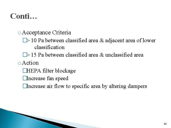
Conti… o Acceptance Criteria �> 10 Pa between classified area & adjacent area of lower classification �> 15 Pa between classified area & unclassified area o Action �HEPA filter blockage �Increase fan speed �Increase air flow to specific area by altering dampers 40
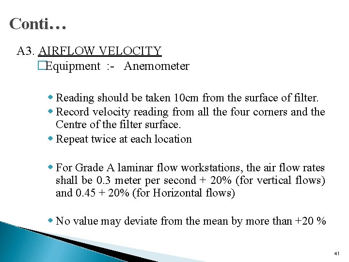
Conti… A 3. AIRFLOW VELOCITY �Equipment : - Anemometer w Reading should be taken 10 cm from the surface of filter. w Record velocity reading from all the four corners and the Centre of the filter surface. w Repeat twice at each location w For Grade A laminar flow workstations, the air flow rates shall be 0. 3 meter per second + 20% (for vertical flows) and 0. 45 + 20% (for Horizontal flows) w No value may deviate from the mean by more than +20 % 41
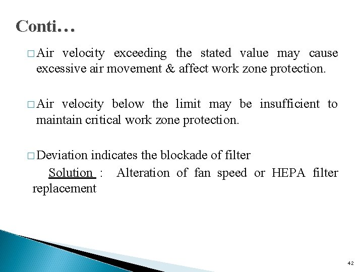
Conti… � Air velocity exceeding the stated value may cause excessive air movement & affect work zone protection. � Air velocity below the limit may be insufficient to maintain critical work zone protection. � Deviation indicates the blockade of filter Solution : Alteration of fan speed or HEPA filter replacement 42
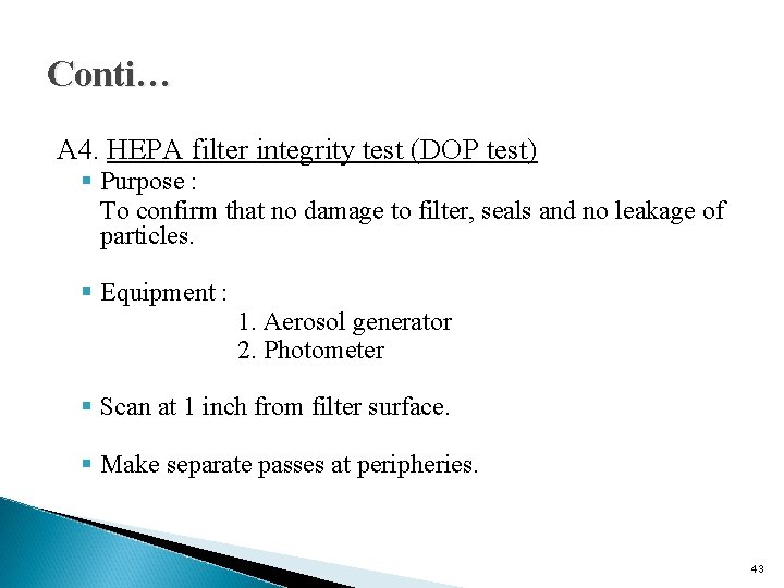
Conti… A 4. HEPA filter integrity test (DOP test) § Purpose : To confirm that no damage to filter, seals and no leakage of particles. § Equipment : 1. Aerosol generator 2. Photometer § Scan at 1 inch from filter surface. § Make separate passes at peripheries. 43
Conti… � Acceptance criteria: An unacceptable leak is defined as a penetration of 0. 03% or more of particle, 0. 3µm and larger than the reference calibration curve for 99. 97% efficient filter 44
Conti… A 5. Temperature and Relative Humidity: § Use a sling psycrometer to measure the dry bulb and wet bulb temperature of the air. § Check the wick of the sling psycrometer, it should be always in wet conditions in order to record correct wet bulb temperature. § Sling the psycrometer in air for about a minute’s time and record the dry bulb and wet bulb temperature. § Check the wet bulb depression i. e. difference between dry bulb and wet bulb temperature. 45
Conti… § Acceptance criteria: Temperature : NMT 27 degree centigrade Humidity : NMT 55 % § Frequency : Daily 46
Conti… A 6. Air change rate: �Measurement of the air supply volume and determination of the air change rate (ACR) is a measure of the frequency of air turnover in the clean room. �This gives some idea as to how quickly contamination may be removed from the clean room provided there is acceptable mixing of air in the room. �The ACR can be determined by measuring the mean air velocity at the supply HEPAs or grilles and calculating the air change rate based on the mean air supply volume. 47
Conti… � Equipment: � Sample Anemometer locations At least four positions are tested across the filter or grille face to obtain the mean supply air velocity. � Frequency of sampling Sch M - 6 Monthly GMP compliance – Quarterly 48
Conti… A 7. MICROBIOLOGICAL TESTS ØSolid growth media (e. g. settle and contact plates) Soybean Casein Digest Agar medium can be used for both Bacteria & Fungi tested. ØThe recommended size of solid media is 90 mm in diameter (for settle plates) Ø 55 mm for contact plates. 49
Conti… � Sampling condition: �Sampling in the at rest condition may be continued at an agreed frequency to monitor baseline contamination levels �The operational conditions and the activities being performed at the time of testing should be recorded � Incubation condition: �Incubation of samples, inverted, at 20 – 25 o C for at least 5 days is suitable for the growth of mould and fungi. �Incubation of samples, inverted, at 30 - 350 C for at least 2 days is suitable for the growth of bacteria. 50
Conti… � Acceptance criteria for Airborne Bioburden test: Critical Environment: no more than 1 CFU/m 3, or 0. 03 CFU/ft 3(USP monograph) � Acceptance criteria for Surface Bioburden test: Critical Environment: no more than 1 CFU/12. 9 cm 2, or 2 in 2 (FDA Aseptic Processing Guidelines) 51
References � Supplementary guidelines on good manufacturing practices for HVAC systems for non-sterile pharmaceutical dosage forms. (WHO Technical Report. Series, No. 937), Annex 2. (2006) � Validation of pharmaceutical process, sterile product 2 nd. Edition, edited by Fredrick J. Carleton, James P. Agalloco, page no. 240 -256. 52
Thank you 53