8085 unit 1 Timing diagram for memory read


 Direct Addressing � In direct addressing mode, the address of the data")
 Immediate addressing � The data is specified in the instruction itself. The")
- Slides: 17
8085 -unit 1 Timing diagram for memory read & memory write cycles
Processor cycles The sequence of operations that a processor has to carry out while executing the instruction is called instruction cylce. Each instruction cycle of a processor in turn consists of a number of machine cycles. The machine cycles are the basic operations performed by the processor. To execute an instruction, the processor executes one or more machine cycles in a particular sequence. The machine cycles of a processor are also called processor cycles. The manufactures of microprocessors define the timings and status of various signals during the processor cycles.
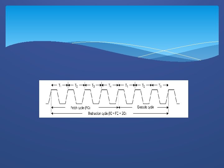
In general, the instruction cycle of an instruction can be divided into two sub cycles. 1) Fetch cycle 2) Execute cycle The fetch cycle is executed to fetch the opcode from memory and the execute cycle is executed to decode the instruction and to perform the work specified by the instruction.
Machine cycles of 8085 The 8085 microprocessor has seven basic machine cycles. They are as follows. 1) Opcode fetch cycle (4 T 0 r 6 T) 2) Memory read cycle (3 T) 3) Memory write cycle(3 T) 4) IO read cycle (3 T) 5) IO write cycle(3 T) 6) Interrupt acknowledge cycle (6 T or 12 T) 7) Bus idle cycle (2 T or 3 T)
The processor takes a definite time to execute the machine cycles. The time taken by the processor to execute a machine cycle is expressed in T states. One T-state is equal to the time period of the internal clock signal of the processor.
Opcode Fetch � This cycle is used to fetch the opcode from the memory � This is the first maschine cycle of every instruction � It is a compulsory machine cycle � It is generally of 4 T states. During T 1 A 15 -A 8 contains the higher byte of the address As ALE is high AD 7 -AD 0 contains the lower byte of the address Since it is an opcode fetch cycle S 1 and S 0 go high Since it a memory operation IO/M goes low During T 2 As ALE goes low address is removed from AD 7 -AD 0 AS RD goes low, data appears on AD 7 -AD 0 During T 3 Data remains on AD 7 -AD 0 till RD is low During T 4 stat is used by the microprocessor to decode the opcode
Memory Read During T 1 A 15 -A 8 contains the higher byte of the address As ALE is high AD 7 -AD 0 contains the lower byte of the address Since it is a memory read cycle S 1 goes high and S 0 go low Since it a memory operation IO/M goes low During T 2 As ALE goes low address is removed from AD 7 -AD 0 AS RD goes low, data appears on AD 7 -AD 0 During T 3 Data remains on AD 7 -AD 0 till RD is low
Memory write During T 1 A 15 -A 8 contains the higher byte of the address As ALE is high AD 7 -AD 0 contains the lower byte of the address Since it is a memory write cycle S 0 goes high Since it a memory operation IO/M goes low During T 2 As ALE goes low address is removed from AD 7 -AD 0 AS RD goes low, data appears on AD 7 AD 0 During T 3 Data remains on AD 7 -AD 0 till WR is low
INTERRUPT � The process of interrupting the normal program execution to carry out a specific task/work is referred to as interrupt. � The interrupt is initiated by a signal generated by an external device or by a signal generated internally to the processor. � When a microprocessor receives an interrupt signal is stops executing current normal program, save the status (or content) of various registers in stack and then the processor executes a subroutine /procedure in order to perform the specific task/work requested by the interrupt. � The interrupts are useful for efficient data transfer between processor and peripheral.
Classification of Interrupts � In general the interrupts can be classified in the following three ways. � iii. Hardware and software interrupts Vectored and non-vectored interrupts Maskable and non-maskable interrupts � Hardware and software interrupts � The interrupts initiated by external hardware by sending an appropriate signal to the interrupt pin of the microprocessor is called hardware interrupt. The 8085 has five interrupt pins TRAP, RST 7. 5, RST 6. 5, RST 5. 5 and INTR. � The software interrupts are program instructions. These instructions are inserted at derived locations in a program. The software interrupts of 8085 are RST 0, RST 1, RST 2, RST 3, RST 4, RST 5, RST 6 and RST 7.
Vectored and non-vectored � When an interrupt signal is accepted by the microprocessor, if the program control automatically branches to a specific address (called vector address) then the interrupt is called vectored interrupts. �In non-vectored interrupt there is no specific address for storing the interrupt service routine. Hence the interrupting device should give the address of the interrupt service routing.
Maskable and Non-maskable � The processors have the facility for accepting or rejecting hardware interrupts. Programming the processor to reject an interrupt is referred to as masking or disabling and programming the processor to accept an interrupt is referred to as unmasking or enabling. � In 8085 the interrupts RST 7. 5, RST 6. 5 and RST 5. 5 can be masked/unmasked using SIM (set interrupt mask) instruction. All the hardware interrupts except TRAP are disabled by executing DI instruction and they are enabled by EI instruction. � The interrupts whose request can be either accepted or rejected by the processor are called maskable interrupts (RST 7. 5, RST 6. 5 , RST 5. 5 and INTR). The interrupts whose request has to be definitely accepted (or cannot be neglected) by the processor are called non-maskable interrupts (TRAP) �
Priorities of the Interrupt �When all the interrupts are enabled, the priority of hardware interrupts from highest to lowest is �TRAP ( it is a non-maskable interrupt) �RST 7. 5 �RST 6. 5 �RST 5. 5 and �INTR �
Addressing modes �Every instruction of a program has to operate on a data. The method specifying the data to be operated by the instructions called addressing. The 8085 supports the following five addressing modes. �Direct addressing �Register indirect addressing �Immediate addressing �Implied addressing/implicit addressing
� i) Direct Addressing � In direct addressing mode, the address of the data is specified in the instruction. The data will be in memory. In this addressing mode, the program instructions and data can be stored in different memory locations. � Example: LDA 1050 H -load the data available in memory location 1050 H in accumulator � ii) Register addressing � In register addressing mode, the instruction specifies the name of the Register in which the data is available. � Example: MOV A, B - move the content of B register to A � iii) Register indirect addressing � In this mode, the instruction specifies the name of the register in which the address of the data is available. Here the data will be in memory and the address will be in a register pair. � Example: MOV A, M - the memory data addressed by HL pair is moved to A-register
�i. V) Immediate addressing � The data is specified in the instruction itself. The data will be a part of the program instruction. �Example: MVI B, 3 EH – move the data 3 EH given in the instruction to B register �v) Implied addressing � The instruction itself specifies the data to operated. �Example: CMA - complement the content of accumulator.