Timing Diagram and Communication Diagram TIMING DIAGRAM Timing


- Slides: 6
Timing Diagram and Communication Diagram TIMING DIAGRAM
�Timing diagrams are a type of interaction diagram. Their purpose is to show the states of an element or elements change over time and how events change those states. �Timing diagrams have many of the same elements that appear in other UML diagrams. They have one or more lifelines, one or more objects (or other UML classifier), two or more states, messages, and so forth. Refer to earlier discussions of these elements for a refresher on their semantics, if required. �Timing diagrams take the UML elements and present them to the user in a different organization.
Generic Timing Diagram � Timing diagrams have one or more lifelines (which look like a horizontal partition) for each object in the diagram. The lifeline name (i. e. , the object name) is shown in the lifeline. The possible states of the object are listed inside the lifeline. Also, a timeline shows how the object changes from one state to another. Events that drive the state changes are shown along the timeline. The horizontal axis shows time and may also show tick marks to help the reader of the diagram better understand specific timing.
� In cases where timing diagrams have many lifelines, or objects that have many states, instead of using a timeline as we did in the previous figures, we can use a more compact representation. Instead of the change of state being indicated as a rise and fall of a timeline, the state changes are merely shown progressing along the horizontal axis.
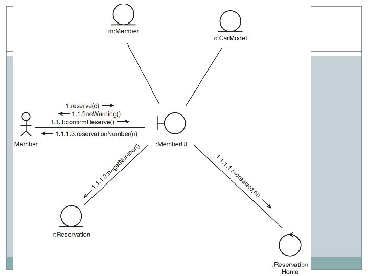
Communication Diagram � If you are familiar with the earlier versions of the UML, you may recognize communication diagrams by their pre-UML 2. 0 name— collaboration diagrams. A communication diagram is a type of interaction diagram that focuses on how objects are linked and what messages they pass as they participate in a specific interaction. � A link may exist between two objects if and only if there is an association between their corresponding classes. The existence of an association between two classes denotes a path of communication (i. e. , a link) between instances of the classes, whereby one object may send messages to another. � In the steady state, there must be consistency between the class structure and the object structure of a system. If we show an operation M being invoked across link L on object B, then B’s specification (or the specification of an appropriate superclass) must contain the declaration of M.