271 Ethernet Surasak Sanguanpong nguanku ac th http


- Slides: 27

/271 Ethernet Surasak Sanguanpong nguan@ku. ac. th http: //www. cpe. ku. ac. th/~nguan Last updated: 27 June 2002 Applied Network Research Group Department of Computer Engineering, Kasetsart University

/272 Ethernet and IEEE 802. 3 Timeline : 1976 Ethernet developed by Xerox Palo Alto Research Center, including Bob Metcalfe (who later founded 3 Com( 10 Mbps Ethernet specification by DEC, Intel, and Xerox : 1980 : 1985 becomes IEEE 802. 3 standard (already widely used before this time( 100 Mbps “Fast Ethernet” standardized in IEEE 802. 3 u : 1995 (already widely used before this time( 1 Gbps “Gigabit Ethernet” IEEE standard issued : 1998 10 Gbps Ethernet under development : 1999 Applied Network Research Group Department of Computer Engineering, Kasetsart University

/273 A Drawing of the First Ethernet System http: //www. ots. utexas. edu/ethernet. html Applied Network Research Group Department of Computer Engineering, Kasetsart University

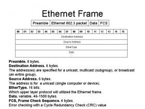
/274 Ethernet frame format IEEE 802. 3 46 -1500 PA SFD 2 DA SA 6 6 LEN 1 7 4 LLC PDU FCS calculation of the FCS 64 -1518 bytes Ethernet 46 -1500 PA 4 DA 2 SA Type 6 6 Data 8 FCS PA : Preamble - 1010 s for synchronization SFD : Start of Frame delimiter -- 10101011 to start frame DA: Destination Address -- MAC address SA: Source Address -- MAC address LEN: Length -- Number of data bytes Type: identify the higher -level protocol LLC PDU+pad -- minimum 46 bytes, maximum 1500 FCS : Frame Check Sequence -- CRC-32 Applied Network Research Group Department of Computer Engineering, Kasetsart University

/275 Ethernet MAC address 46 1 I/G U/L 1 46 -bit address 6 byte ethernet addr 3 Bytes vendor 3 Bytes card no. I/G =0 Individual address I/G =1 Group address U/L=0 Global administered address U/L=1 Local administered address Unicast : define a single destination Broadcast : FFFF each station on the network receive and accept frames multicast : a group address defines multiple recipient Applied Network Research Group Department of Computer Engineering, Kasetsart University

/276 Ethernet architecture station interface data encapsulation Data link layer NIC link management encoding and decoding AUI cable Physical layer transmission and receipt tap transceiver “ 0. 5 Coax Applied Network Research Group Department of Computer Engineering, Kasetsart University

/277 IEEE 802. 3 Cable Types Name 10 Base 5 10 Base 2 10 Base. T 10 Base. FP 10 Base. FL 10 Base. FB 10 Broad 36 Cable Max. Length Nodes/segment thick coax 500 meters 100 thin coax 185 meters 30 twisted pair 100 meters 1 fiber optic 1 km 33 passive fiber optic 2 km 1 point-to-point coax 3. 6 km ? broadband 10 Base 5 data rate in Mbps Applied Network Research Group baseband or broadband cable type or length limit Department of Computer Engineering, Kasetsart University

/278 10 Base 5 • tap : by insertion, cable does not need to be cut • transceiver : send/receive, collision detection, electronics isolation • AUI : Attachment Unit Interface, a 5 -pair cable up to 50 meters long 0. 5 inch coax • Use for backbone networks maximum segment length=500 m maximum number of stations per segment=100 vampire tap transceiver cable terminator repeater DB-15 connector AUI cable DB-15 connector distance between stations must be a multiple of 2. 5 m maximum network distance = 2. 5 km 5)segments : 1000 stations( Applied Network Research Group NIC Department of Computer Engineering, Kasetsart University

/279 10 Base 2 0. 25 inch coax (RG 58( • tap: BNC connector, must splice cable • No drop (AUI) cable • use: for connecting workstations • cheaper, easier to use than thick coax, but more signal attenuation BNC T-connector NIC maximum segment length=185 m maximum number of stations per segment=30 repeater minimum distance between two stations = 0. 5 m maximum network distance between two stations = 925 m Applied Network Research Group Department of Computer Engineering, Kasetsart University

/2710 10 Base. T • • uses 4 -pair twisted pair cable (Category-3, -4, or -5 ( a hub functions as a repeater fewer cable problems, easier to troubleshoot than coax cable length at most 100 meters due to high attenuation (with good Category-5 cable you can go longer( • most commonly used cable today hub maximum segment length = 100 m Applied Network Research Group NIC Department of Computer Engineering, Kasetsart University

/2711 10 Base. F • 10 Base. F specification enable long distance connections with • the use of optical fiber. Three standards are: • 10 Base. FP - 10 -Mbps fiber-passive baseband Ethernet specification using fiber-optic cabling. It organizes a number of computers into a star topology without the use of repeaters. 10 Base. FP segments can be up to 500 meters long • 10 Base. FL - asynchronous point-to-point link between a station and a hub or repeater, up to 2 km. • 10 Base. FB - synchronous point-to-point link between repeaters, up to 2 km long, cascaded repeaters are allowed. Signal is retimed at each repeater Applied Network Research Group Department of Computer Engineering, Kasetsart University

/2712 Signal Encoding l Manchester encoding ensures a transition every bit n n : 0 high-to-low : 1 low-to-high 1 1 0 0 0 1 1 0 0 m. A 0 V (high( 90 -m. A 2. 2 -V (low( 100 ns Applied Network Research Group Department of Computer Engineering, Kasetsart University

/2713 Carrier Sense Multiple Access Carrier sense: station listens to media before transmitting Multiple access: multiple stations may access at same time Media idle? YES Transmit immediately Applied Network Research Group Media idle? NO -- wait Listen until the media is idle, then transmit Department of Computer Engineering, Kasetsart University

/2714 Collision More than one station may send a frame during overlapping times. How does a station know that a collision occurred? What does the station do after a collision? Applied Network Research Group Department of Computer Engineering, Kasetsart University

/2715 How does a node detect a collision? Transceiver: A node monitors the media while transmitting. If the observed power is more than transmitted power + attenuated reflection of its own signal, it indicates a collision. Transmitted signal Collision! Observed signal Hub: if input occurs simultaneously on two ports, it indicates a collision. Hub sends a collision presence signal on all ports. Simultaneous input on two ports Applied Network Research Group Output “collision presence” on all ports Department of Computer Engineering, Kasetsart University

/2716 Retransmission after a collision Exponential backoff rule: l Choose k = 0 or 1 at random. Wait k x 51. 2 msec. l l If collision, then choose k = 0, 1, 2, 3 at random l l l wait k x 51. 2 msec. retransmit frame when media is idle. If collision, then choose k = 0, . . . , 15 at random l l wait k x 51. 2 msec. retransmit frame when media is idle. If collision, then choose k = 0, . . . , 7 at random l l retransmit frame when media is idle. wait k x 51. 2 msec. retransmit frame when media is idle. . Double the wait interval until frame is transmitted or it becomes 0 - 1023. If frame is not transmitted within 16 attempts, give up and report failure. Applied Network Research Group Department of Computer Engineering, Kasetsart University

/2717 Collision Detection Rules. 1 Stations must listen to the cable while transmitting in order to detect a collision. . 2 A frame must be at least 64 bytes (512 bits, 51. 2 microseconds) long to ensure sender “hears” a collision before he finishes. (The transmission time must be more than the RTT(. . 3 If a collision is detected, send a brief jamming signal and then wait before retransmitting. Jamming signal Applied Network Research Group Jamming signal Department of Computer Engineering, Kasetsart University

/2718 Minimum frame size A and B located at the far ends of the cable A A (1) packet starts at time 0 (3)B send packet ; collision occurs at t B B A A (2)packet almost at B at t-d B (4)jam signal gets back to A at 2 t B l A frame must take more than 2 t to send to prevent the situation that the sender incorrectly concludes that the frame was successfully sent. l This slot times equal 51. 2 ms corresponds to 512 bit (64 bytes( l The minimum frame length is 64 bytes (excluding preamble( l This answers why data field must have 46 bytes minimum Applied Network Research Group Department of Computer Engineering, Kasetsart University

/2719 Worst Case Collision Timing 500 meters 2, 500 meters Assume delay for repeater is 1 msec; for transceiver 0. 5 msec. Component Propagation Time Microsecs Five 500 meter segments 2500 m/0. 77 c 10. 8 Four repeaters 4 x 1 msec 4. 0 Nine 50 meter AUI cables 450 m/0. 65 c 2. 3 Nine transceivers 9 x 0. 5 msec 4. 5 Total one-way time 21. 6 Applied Network Research Group Department of Computer Engineering, Kasetsart University

/2720 Worst Case Collision Timing (cont(. 500 meters 43. 2 microsecond RTT Under these assumptions, the round trip time would be 43. 2 microseconds. Allowing some tolerance for equipment, IEEE chose 51. 2 microseconds, equal to 512 bit-times, as the collision detection interval. This is why all frames must be at least 512 bits (64 bytes) long. Applied Network Research Group Department of Computer Engineering, Kasetsart University

/2721 Late Collision A late collision occurs when sender finishes transmission before detecting collision presence. Usual causes: • cable too long • too many repeaters between stations Solution: higher layer protocol must detect packet loss and retransmit. l Applied Network Research Group Department of Computer Engineering, Kasetsart University

/2722 Interframe Gap FRAME 96 bit-time interframe gap A sender must wait 96 bit-times between frames to give other stations an opportunity to transmit. A 96 bit-time delay is 9. 6 microseconds on 10 Mbps ethernet. Applied Network Research Group Department of Computer Engineering, Kasetsart University

/2723 Ethernet Performance (cont(. Tanenbaum (1996) has plotted the utilization as a function of n (number of stations) and F (average frame size: ( 85% Ethernet channel utilization 27% Number of stations trying to send Applied Network Research Group Department of Computer Engineering, Kasetsart University

/2724 Ethernet Speed and Collision Detection Max Network Size So, without any delay due to repeaters or network interfaces, the largest network size in a shared media configuration is : Ethernet Speed 10 Mbps 100 Mbps 1 Gbps Minimum Frame Size Min Frame TX Time Upper Bound on Network Size 64 byte 51. 2 microsec 5. 12 microsec 0. 512 microsec 5, 120 m 512 m 51 m Next we will see how the fast and gigabit ethernet standards address these limits. Applied Network Research Group Department of Computer Engineering, Kasetsart University

/2725 Fast Ethernet l l l l 100 Mbps transmission rate same frame format, media access, and collision detection rules as 10 Mbps ethernet can combine 10 Mbps ethernet and fast ethernet on same network using a switch, or combined hub+switch 64 byte minimum frame ==> 5. 12 microsecond xmit time 96 bit interframe gap ==> 0. 96 microsecond network diameter must be smaller than 10 Mbps ethernet media: twisted pair or fiber optic cable (no coax( Applied Network Research Group Department of Computer Engineering, Kasetsart University

/2726 Gigabit Ethernet l l l same frame format, media access, and collision detection rules as previous ethernet generations same 64 byte minimum frame and 96 bit interframe gap can combine 10 Mbps, 100 Mbps, and gigabit ethernet on same network (but not on same cable) using a switch 200 meter network diameter (using UTP) requires a minimum transmission time of 512 bytes on shared media several media types: UTP, shielded copper short-wave fiber optics long-wave fiber optics Applied Network Research Group Department of Computer Engineering, Kasetsart University

/2727 Gigabit Ethernet Media Types 1000 base. LX 1300 nm laser 1000 base. SX 850 nm LED 9 micron single mode fiber 50 or 62. 5 micron multimode fiber 400 -500 MHz modal bandwidth 550 m 50 micron multimode 500 MHz modal bandwidth 550 m 50 micron multimode 400 MHz modal bandwidth 500 m 62. 5 micron multimode 200 MHz modal bandwidth 275 m 62. 5 micron multimode 160 MHz modal bandwidth 1000 base. T 1000 base. CX 5 km 4 pair Cat-5 UTP STP 220 m 100 m 25 m Applied Network Research Group Department of Computer Engineering, Kasetsart University
 Switched ethernet vs shared ethernet
 Cybr 271
 271 21
 Ssi msi lsi vlsi ulsi classification
 Rounding to the nearest ten thousand
 230 birler basamağına yuvarlama
 Ddu 271
 Nmos inverter with resistive load
 Mastering physics login
 Nearest ten thousand
 Http //mbs.meb.gov.tr/ http //www.alantercihleri.com
 Siat.ung.ac.id
 N-unicast
 Classic ethernet physical layer
 100 gbps ethernet
 Ethernet over sdh
 Gigabit ethernet passive optical network
 Rockwell automation
 Ethernet code b
 Gigabit ethernet u/ddm
 Ethernet switch tester
 Ethernet vs wifi
 Trame ethernet
 Ethernet frame
 Arduino gigabit ethernet
 1172011
 What is ethernet and token ring
 Facility monitoring system
