WIR SCHAFFEN WISSEN HEUTE FR MORGEN Michael Eichin
- Slides: 18
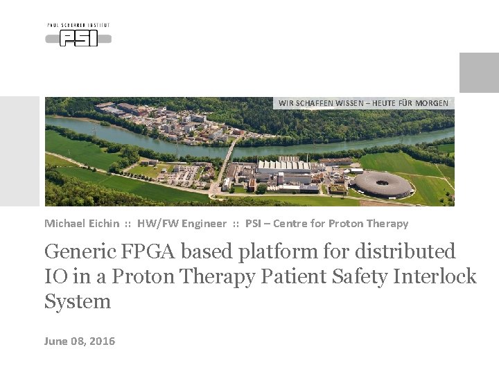
WIR SCHAFFEN WISSEN – HEUTE FÜR MORGEN Michael Eichin : : HW/FW Engineer : : PSI – Centre for Proton Therapy Generic FPGA based platform for distributed IO in a Proton Therapy Patient Safety Interlock System June 08, 2016
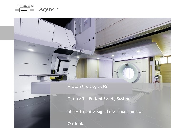
Agenda Proton therapy at PSI Gantry 3 – Patient Safety System SCB – The new signal interface concept Outlook
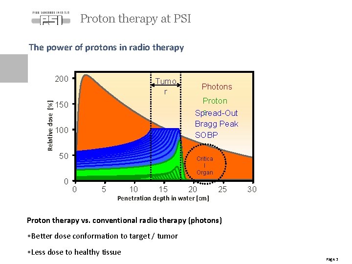
Proton therapy at PSI The power of protons in radio therapy Relative dose [%] 200 Tumo r Proton s Spread-Out Bragg Peak SOBP 150 100 50 0 Photons Critica l Organ 0 5 10 15 20 Penetration depth in water [cm] 25 30 Proton therapy vs. conventional radio therapy (photons) • Better dose conformation to target / tumor • Less dose to healthy tissue Page 3
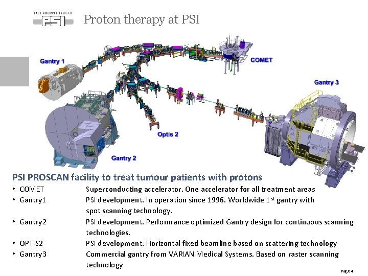
Proton therapy at PSI PROSCAN facility to treat tumour patients with protons • COMET • Gantry 1 • Gantry 2 • OPTIS 2 • Gantry 3 Superconducting accelerator. One accelerator for all treatment areas PSI development. In operation since 1996. Worldwide 1 st gantry with spot scanning technology. PSI development. Performance optimized Gantry design for continuous scanning technologies. PSI development. Horizontal fixed beamline based on scattering technology Commercial gantry from VARIAN Medical Systems. Based on raster scanning technology Page 4
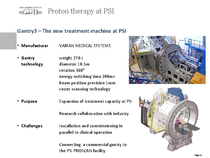
Proton therapy at PSI Gantry 3 – The new treatment machine at PSI • Manufacturer VARIAN MEDICAL SYSTEMS • Gantry technology weight 270 t diameter 10. 5 m rotation 360° energy switching time 200 ms beam position precision 1 mm raster scanning technology • Purpose Expansion of treatment capacity at PSI Research collaboration with industry • Challenges Installation and commissioning in parallel to clinical operation Connecting a commercial gantry to the PSI PROSCAN facility Page 5
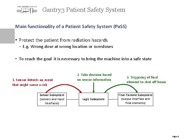
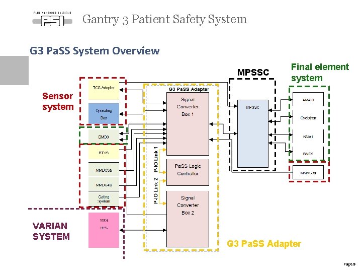
Gantry 3 Patient Safety System Main functionality of a Patient Safety System (Pa. SS) • Protect the patient from radiation hazards - E. g. Wrong dose at wrong location or overdoses • To reach the goal it is necessary to bring the machine into a safe state 1. Sensor detects an event that might cause a risk Sensor Subsystem (sensors and input interfaces) 2. Take decision based on sensor information Logic Subsystem 3. Triggering of final element to shut off beam Final Element Subsystem (output interface and final elements) Page 6
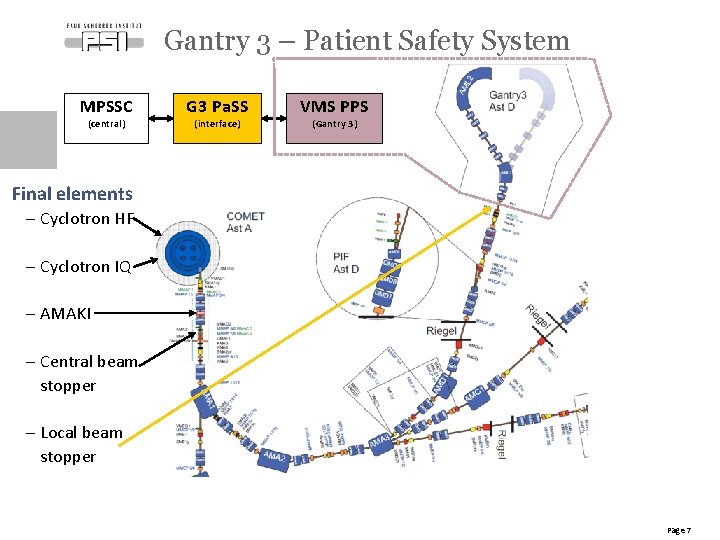
Gantry 3 – Patient Safety System MPSSC G 3 Pa. SS VMS PPS (central) (interface) (Gantry 3) Final elements - Cyclotron HF - Cyclotron IQ - AMAKI - Central beam stopper - Local beam stopper Page 7
Gantry 3 Patient Safety System G 3 Pa. SS System Overview MPSSC Final element system Sensor system VARIAN SYSTEM G 3 Pa. SS Adapter Page 8
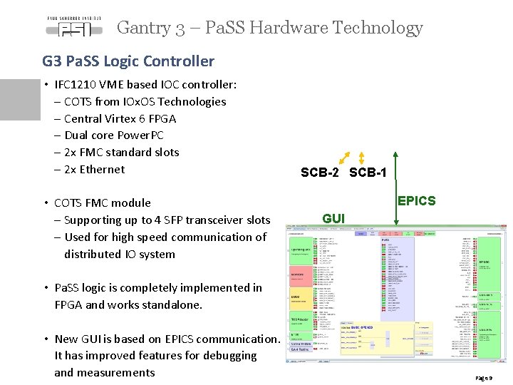
Gantry 3 – Pa. SS Hardware Technology G 3 Pa. SS Logic Controller • IFC 1210 VME based IOC controller: - COTS from IOx. OS Technologies - Central Virtex 6 FPGA - Dual core Power. PC - 2 x FMC standard slots - 2 x Ethernet IFC 1210 • COTS FMC module - Supporting up to 4 SFP transceiver slots - Used for high speed communication of distributed IO system FPGA FMC SCB-2 SCB-1 EPICS GUI • Pa. SS logic is completely implemented in FPGA and works standalone. • New GUI is based on EPICS communication. It has improved features for debugging and measurements Page 9
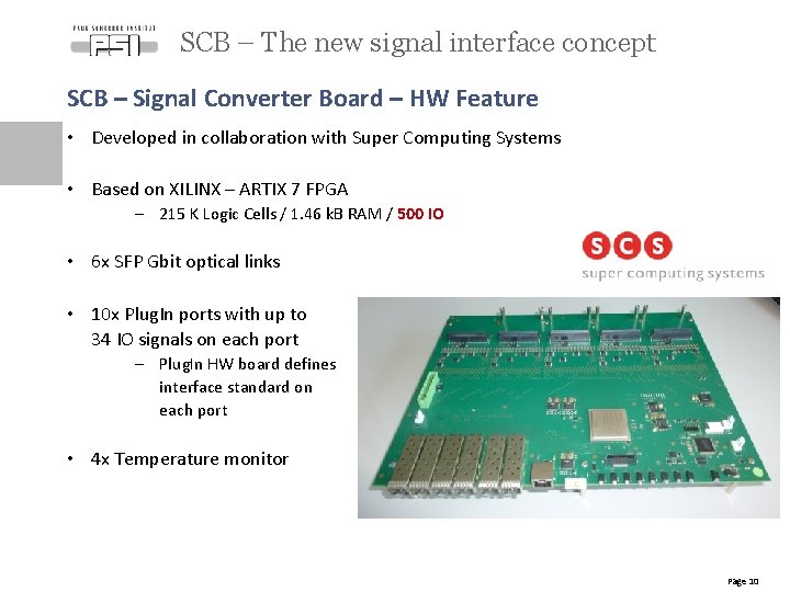
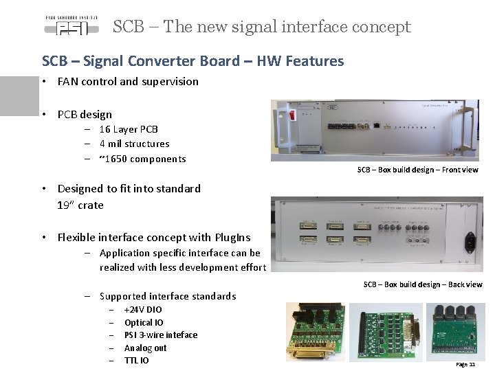
SCB – The new signal interface concept SCB – Signal Converter Board – HW Feature • Developed in collaboration with Super Computing Systems • Based on XILINX – ARTIX 7 FPGA - 215 K Logic Cells / 1. 46 k. B RAM / 500 IO • 6 x SFP Gbit optical links • 10 x Plug. In ports with up to 34 IO signals on each port - Plug. In HW board defines interface standard on each port • 4 x Temperature monitor Page 10
SCB – The new signal interface concept SCB – Signal Converter Board – HW Features • FAN control and supervision • PCB design - 16 Layer PCB - 4 mil structures - ~1650 components SCB – Box build design – Front view • Designed to fit into standard 19” crate • Flexible interface concept with Plug. Ins - Application specific interface can be realized with less development effort - Supported interface standards - +24 V DIO Optical IO PSI 3 -wire inteface Analog out TTL IO SCB – Box build design – Back view Page 11
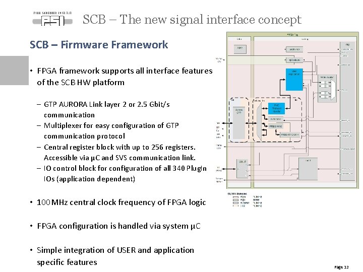
SCB – The new signal interface concept SCB – Firmware Framework • FPGA framework supports all interface features of the SCB HW platform - GTP AURORA Link layer 2 or 2. 5 Gbit/s communication - Multiplexer for easy configuration of GTP communication protocol - Central register block with up to 256 registers. Accessible via µC and SVS communication link. - IO control block for configuration of all 340 Plug. In IOs (application dependent) • 100 MHz central clock frequency of FPGA logic • FPGA configuration is handled via system µC • Simple integration of USER and application specific features Page 12
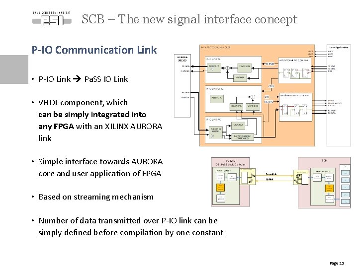
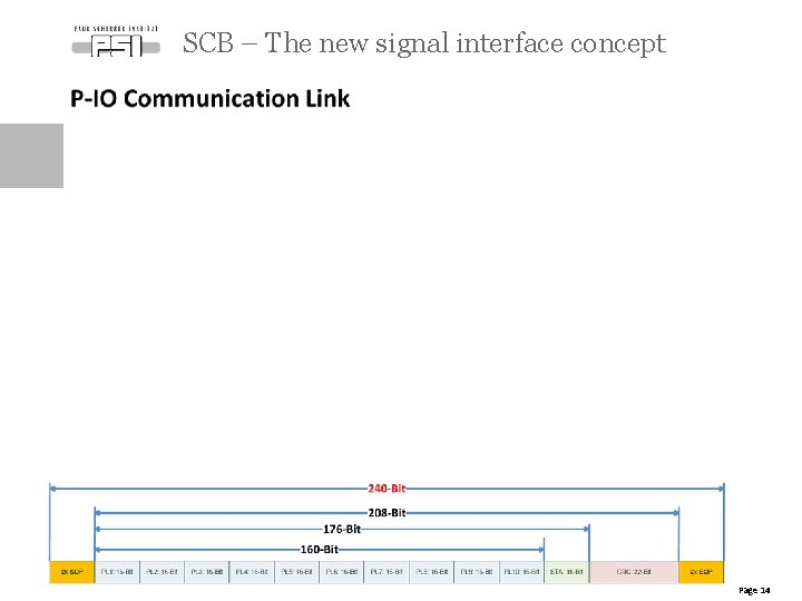
SCB – The new signal interface concept P-IO Communication Link • P-IO Link Pa. SS IO Link • VHDL component, which can be simply integrated into any FPGA with an XILINX AURORA link • Simple interface towards AURORA core and user application of FPGA • Based on streaming mechanism • Number of data transmitted over P-IO link can be simply defined before compilation by one constant Page 13
SCB – The new signal interface concept Page 14
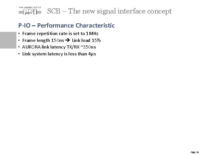
SCB – The new signal interface concept P-IO – Performance Characteristic • • Frame repetition rate is set to 1 MHz Frame length 150 ns Link load 15% AURORA link latency TX/RX ~350 ns Link system latency is less than 4µs Page 15
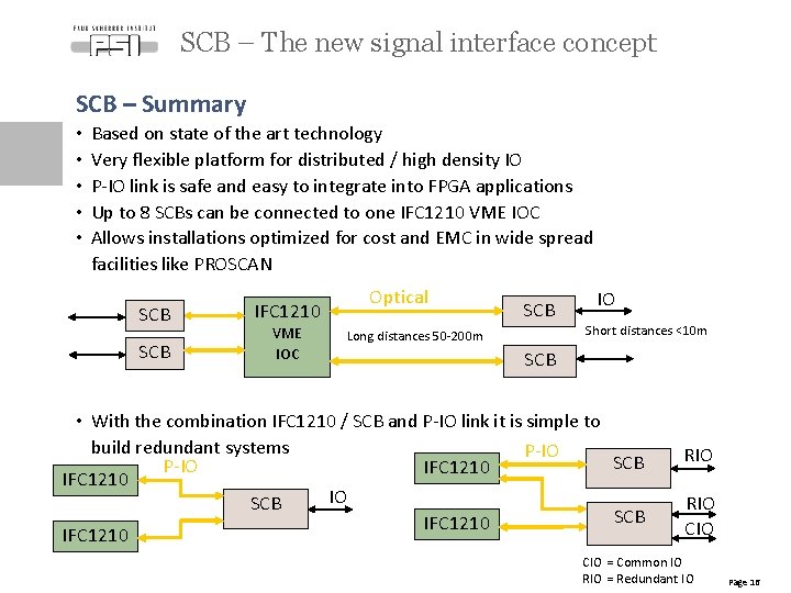
SCB – The new signal interface concept SCB – Summary • • • Based on state of the art technology Very flexible platform for distributed / high density IO P-IO link is safe and easy to integrate into FPGA applications Up to 8 SCBs can be connected to one IFC 1210 VME IOC Allows installations optimized for cost and EMC in wide spread facilities like PROSCAN SCB IFC 1210 VME IOC Optical SCB IO Short distances <10 m Long distances 50 -200 m SCB • With the combination IFC 1210 / SCB and P-IO link it is simple to build redundant systems P-IO SCB P-IO IFC 1210 IO SCB IFC 1210 RIO CIO = Common IO RIO = Redundant IO Page 16
Outlook Where is the project today? • Technical commissioning of Gantry 3 started in November 2015 • G 3 Pa. SS is in operation since November 2015 • No changes on the logic since February 2016 • Final integration tests have to be done • 1 st patient is planned for early 2017 Future projects • Platform can be used for a technology upgrade of existing PSI Pa. SS systems • Optical P-IO link communication can be used for performance optimization of the beam position verification system in Gantry 2 • Flexible SCB – IO concept allows design of standalone controller independent of the VME platform. Page 17
Thank you for your attention Page 18