What is wave front The Cartesian ellipsoid produces


 Sphere, cylinder")
, a low")


 • higher-orders (HOA RMS) •")
: 2064 -74. Normal-eye Zernike coefficients and root-mean-square")
 2 x mean 6. 0 0. 33 0.")


 and images the")


 FMOS is a powerful wide-field spectroscopy system that enables near-infrared")


- Slides: 32
What is wave front
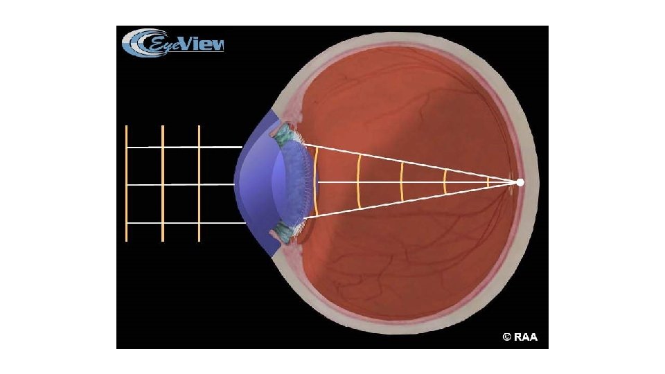
The Cartesian ellipsoid produces a stigmatic image of only one object point Normal eye and most of optical systems are not free from aberration.
Reference sphere: a circular arc centered on the image point with a radius equal to the image distance
Wave front aberration: the difference between the reference sphere and the wave front
Optical aberrations Approximately 80% - 90% of visual aberration error can be explained through the low order (first and second order) aberrations : 1 st Order Aberation =Tilt (prism) 2 nd Order Aberation = Defocus (sphere) and cylinder The less frequent high order aberrations represent the residual 10% to 20%: (mostly induced surgically) 3 rd Order Aberation = Coma and trefoil 4 th Order Aberation = Spherical and quadrafoil 5 th Order Aberation = Distortions / irregular astigmatism 6 th to 8 th Order Aberation = Significantly increasing levels of irregular astigmatism, Diffraction Chromatic aberrations
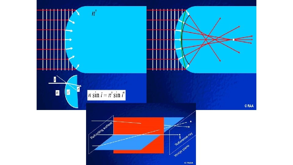
Refractive errors of the eye can be described in terms of the shape of a wavefront of light that has passed through the eye's optics. With aberration-free optics, wavefronts exiting the eye are perfectly flat (top). Refractive errors, such as myopia, distort the wavefront (bottom). Other refractive errors, includinghigher-order aberrations, cause wavefront distortions that differ in shape from those seen in simplemyopia
The difference between the wave front and the reference sphere is the Wave front aberration
What are aberrometers? • • Instruments that measure refractive errors (super auto-refractors) Sphere, cylinder + HOAs(Higher-order aberrations) ≠ corneal topography! COAS
Measurement of optical aberrations Wave front analyzer systems. Hartman-shack aberrometry (outgoing aberronetry), a low intensity laser beam is directed onto the retina, a lens array focuses the outcoming light rays onto a photoreceptor (CCD) . Tscherning aberrometry (ingoing aberrometry), a collimated beam is passed through a mask of holes and into the eye, a high magnification camera captures the image onto the retina. Retina ray tracing technique (ingoing aberrometry), a laser beam is used to scan across the pupil in a sequential manner, each position focus a single point on fovea
History of HO aberrometry 1970 s and 80 s, Strategic defense • Refraction through the atmosphere • Astronomy Reagan • • Adaptive optics (AO) • Shack-Hartman wavefront sensor Shack
Zernike analysis & Zernike coefficients Breaks the wave front down into the Standard Zernike modes or Magnitude & axis form Each Zernike mode = one aberration Z analysis also provides a value for each. mode: Units in microns, ±sign Absolute Zernike coefficient = magnitude Must specify pupil size Zernike
RMS wave front error Total aberrations (LOAs + HOAs) • higher-orders (HOA RMS) • just third-order aberrations, etc. • The basic data = individual Zernike coefficients •
J Cataract Refract Surg. 2006 Dec; 32(12): 2064 -74. Normal-eye Zernike coefficients and root-mean-square wavefront errors. Salmon TO, van de Pol C. METHODS: Data were collected from 10 laboratories that measured higher-order aberrations (HOAs) in normal, healthy adult eyes using Shack-Hartmann aberrometry (2560 eyes of 1433 subjects). Signed Zernike coefficients were scaled to pupil diameters of 6. 0 mm, 5. 0 mm, 4. 0 mm, and 3. 0 mm and corrected to a common wavelength of 550 nm. The mean signed and absolute Zernike coefficients across data sets were compared. Then, the following were computed: overall mean values for signed and absolute Zernike coefficients; polar Zernike magnitudes and RMS values for coma-like aberrations (Z(3)(+/-1) and Z(5)(+/-1) combined); spherical-like aberrations (Z(4)(0) and Z(6)(0) combined); and 3 rd-, 4 th-, 5 th-, and 6 th-order, and higher-order aberrations (orders 3 to 6). RESULTS: The different data sets showed good agreement for Zernike coefficients values across most higher-order modes, with greater variability for Z(4)(0) and Z(3)(-1). The most prominent modes and their mean absolute values (6. 0 -mm pupil) were, respectively, Z(3)(-1) and 0. 14 microm, Z(4)(0) and 0. 13 microm, and Z(3)(-3) and 0. 11 microm. The mean total higher-order RMS was 0. 33 microm. CONCLUSIONS: There was a general consensus for the magnitude of HOAs expected in normal adult human eyes. At least 90% of the sample had aberrations less than double the mean values reported here. These values can serve as a set of reference norms.
HOA results Pupil diameter Mean (µm) 2 x mean 6. 0 0. 33 0. 66 5. 0 0. 19 0. 38 4. 0 0. 10 0. 20 Prominent individual HOAs (6. 0 -mm pupil) • Z 3 -1 (vertical coma) = 0. 14 • Z 40 (spherical aberration) = 0. 13 • Z 3 -3 (oblique trefoil) = 0. 11 •
0 Magnitude & axis form piston Z 0 1 prism Z 11 2 sphere Z 20 3 coma trefoil Z 31 4 order (n) astigmatis Z 22 m spherical aberration Z 33 quadrafoil Z 40 Z 42 Z 44 secondary astigmatism
Z 1 -1 Combined Zernike modes Z 1 1 1 Z 11 Z 2 -2 Z 2 0 Z 2 2 2 Z 22 Z 3 -3 Z 31 3 order (n) Z 3 1 Z 3 -1 Z 33
Conventional Rx: +0. 25 -0. 75 x 111 Zernike coefficients 2 nd order Mode: Z 2 -2 Z 20 Z 22 Coefficient (µm): . 56. 27. 64 Rx: +0. 19 - 0. 67 x 111 Pupil diameter: 5. 6 mm Total RMS: 0. 76 µm Higher-order RMS: 0. 51 µm 3 rd order 4 th order Z 3 -3 Z 3 -1 Z 33 Z 4 -4 Z 4 -2 Z 40 Z 42 Z 44 -. 03. 07 -. 05. 06 Unit = µm . 03. 04 . 11 + or - 0 -. 08 values
HO RMS & pupil size
Tscherning aberroscope. Modern techniques use a projected grid of dots (left) and images the resultant pattern distortion on the retina (right) to determine aberrations.
The MTF: measures the contrast loss with increasing spatial frequency when transferring an object to animage through an aberrated optical system. Spatial frequency is defined by the number of cycles (line pairs) per distance. It is known that fine details (high spatial frequencies) are the first to be affected when the quality of an optical system is degraded. As a functionof the diffraction and the importance of optical aberrationsof the system studied, it is possible todetermine the fashion in which the optical system reducesthe contrast between specific spatial frequenciesand to deduce the optical quality of the image that isrendered.
One disadvantage of Zernike is that in highly aberratedeyes, such as in keratoconus, the Zernike decompositioninvolves the creation of numerous basisf unctions that require complex calculations to representt accurately. The Fourier polynomial system was later suggested as an alternative to decompose the wavefront map based on the claim that given a limitedset of basis functions, the Fourier expansionwould be more efficient and more reliable in reproducingthe overall wavefront map
Fiber Multi-Object Spectrograph (FMOS) FMOS is a powerful wide-field spectroscopy system that enables near-infrared spectroscopy of over 100 objects at a time. It is composed of three subsystems: 1) an infrared unit at prime focus (PIR) that includes a wide-field corrector lens system and fiber positioning system ("Echidna"), 2) a fiber bundle unit of 400 optical fibers, and 3) two spectrographs. Echidna can precisely position all 400 fibers in just 15 minutes. This high speed for repositioning allows observers to reconfigure Echidna, observe multiple fields during a night and rapidly observe hundreds of faint targets that can be compiled as data for statistical analysis. . .
An exciting new promising application is the combination of wavefront with other technologies such as topography, biometry, Scheimpflug, and/or optical coherence tomography, and this is likely to refine the modeling of the eye for ideal refractive correction. Other areas related to wavefront technology, such as enhancing the precision and reproducibility of wavefront simulations with the adaptive optics visual stimulator and a better delivery system of the desired wavefront pattern to the cornea with enhanced laser technology, can be further developed. In this way, the initial quest for super vision with customized laser vision correction might someday be delivered, with the possibility of achieving better results than the initial CDVA.
Clinical HO aberrometry • Laser refractive surgery • Large HOAs • Clinical aberrometry • Wavefront-guided LASIK COAS
3. How do they work? • • • Light is projected in. Reflect off the retina Light passes through the eye’s optics. Catch the light. Analyze it. Reconstruct the optical wavefront’s shape
Summary 4. Interpreting the data • Aberrometers measure wavefronts • Wavefront - distorted by aberrations • Zernike analysis - which aberrations are present • Zernike coefficients - how bad they are • Data in microns, with ± signs • RMS - magnitude of grouped aberrations • Pupil size, pupil size !
5. Diagnosis - what’s normal? • Aberrometry - diagnoses abnormal optics • Ideal eye = zero aberrations, but … • every eye has some aberrations. • So, are those Zernike or RMS values good or bad? • Need reference norms
OCO Norms • • • JCRS Dec 2006 2, 560 normal eyes 9 sites Zernike & RMS norms Data on www Google “Dr. Salmon”
Downloadable info • • Full article in PDF Norms table - PDF & Excel Signed Zernike coefficients Absolute values Combined (polar) Zernike modes RMS for HOA and orders 3, 4, 5, 6 http: //arapaho. nsuok. edu/~salmonto