W 10 D 1 Inductance and Magnetic Field


- Slides: 48
W 10 D 1: Inductance and Magnetic Field Energy Today’s Reading Assignment W 10 D 1 Inductance & Magnetic Energy Course Notes: Sections 11. 1 -3 1
Announcements Math Review Week 10 Tuesday from 9 -11 pm in 32 -082 PS 7 due Week 10 Tuesday at 9 pm in boxes outside 32 -082 or 26 -152 Next Reading Assignment W 10 D 2 DC Circuits & Kirchhoff’s Loop Rules Course Notes: Sections 7. 1 -7. 5 Exam 3 Thursday April 18 7: 30 pm – 9: 30 pm 2
Outline Faraday Law Problem Solving Faraday Law Demonstrations Mutual Inductance Self Inductance Energy in Inductors Transformers 3
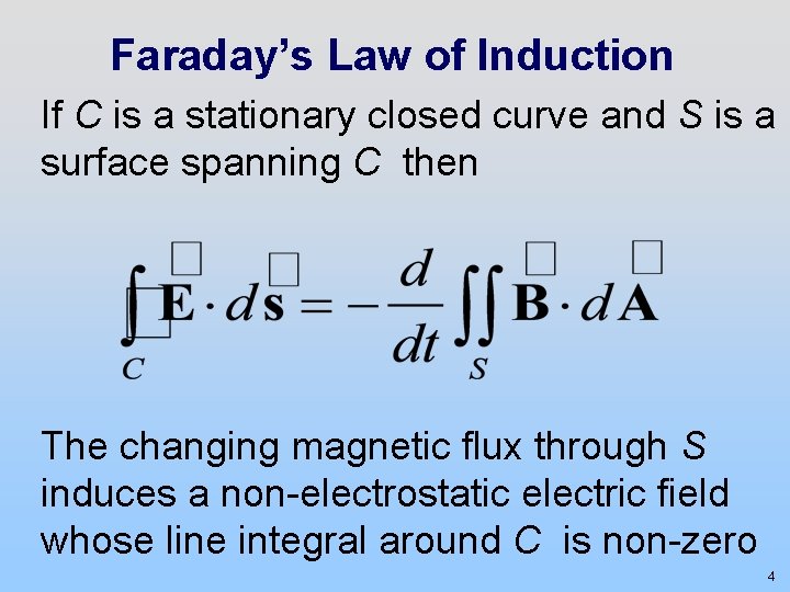
Faraday’s Law of Induction If C is a stationary closed curve and S is a surface spanning C then The changing magnetic flux through S induces a non-electrostatic electric field whose line integral around C is non-zero 4
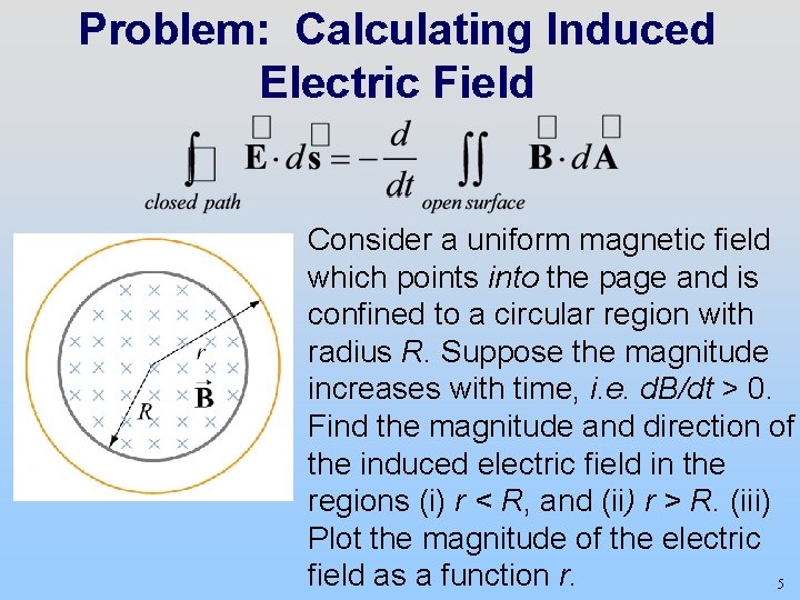
Problem: Calculating Induced Electric Field Consider a uniform magnetic field which points into the page and is confined to a circular region with radius R. Suppose the magnitude increases with time, i. e. d. B/dt > 0. Find the magnitude and direction of the induced electric field in the regions (i) r < R, and (ii) r > R. (iii) Plot the magnitude of the electric field as a function r. 5
Faraday’s Law Demonstrations 6
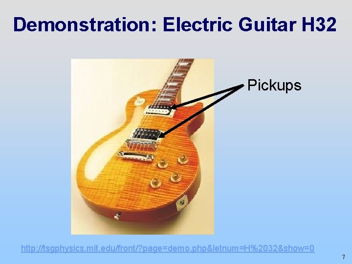
Demonstration: Electric Guitar H 32 Pickups http: //tsgphysics. mit. edu/front/? page=demo. php&letnum=H%2032&show=0 7
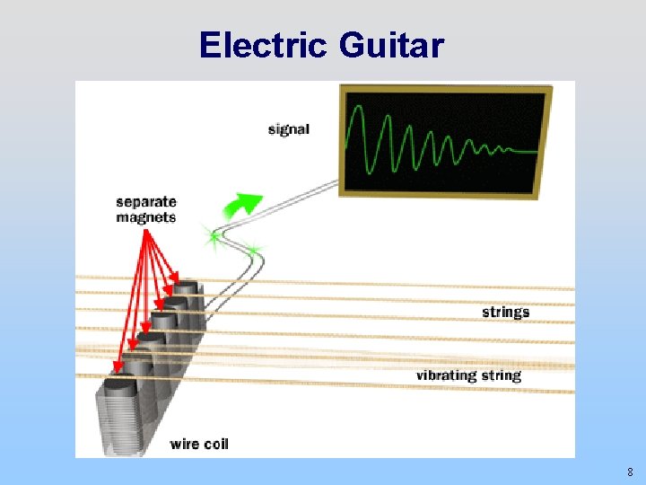
Electric Guitar 8
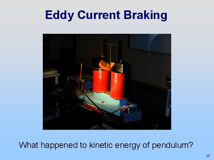
Demonstration: 32 -082 Aluminum Plate between Pole Faces of a Magnet H 14 http: //tsgphysics. mit. edu/front/? page=demo. php&letnum=H 14&show=0 26 -152 Copper Pendulum Between Poles of a Magnet H 13 http: //tsgphysics. mit. edu/front/? page=demo. php&letnum=H 13&show=0 9
Eddy Current Braking What happened to kinetic energy of pendulum? 10
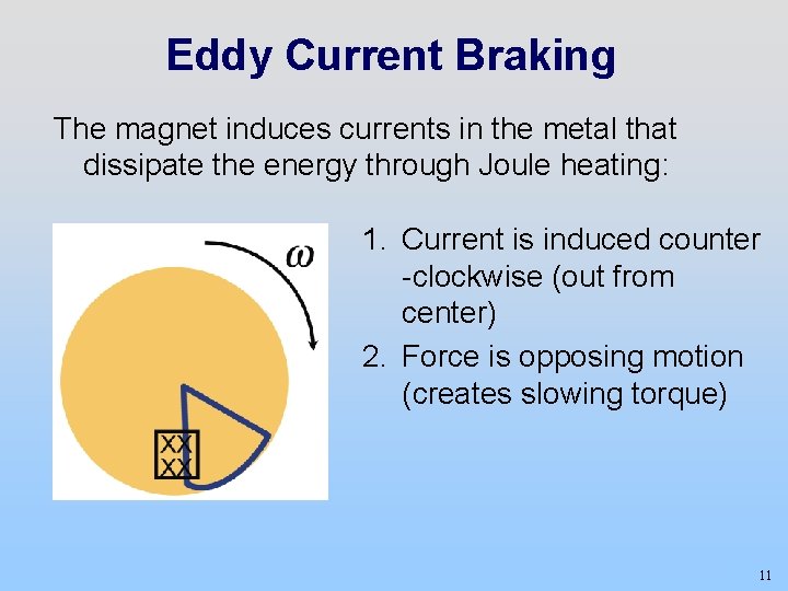
Eddy Current Braking The magnet induces currents in the metal that dissipate the energy through Joule heating: 1. Current is induced counter -clockwise (out from center) 2. Force is opposing motion (creates slowing torque) 11
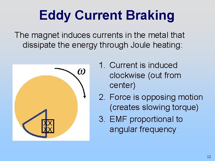
Eddy Current Braking The magnet induces currents in the metal that dissipate the energy through Joule heating: 1. Current is induced clockwise (out from center) 2. Force is opposing motion (creates slowing torque) 3. EMF proportional to angular frequency 12
Demonstration: 26 -152 Levitating Magnet H 28 http: //tsgphysics. mit. edu/front/? page=demo. php&letnum=H 28&show=0 32 -082 Levitating Coil on an Aluminum Plate H 15 http: //tsgphysics. mit. edu/front/? page=demo. php&letnum=H 15&show=0 13
Mutual Inductance 14
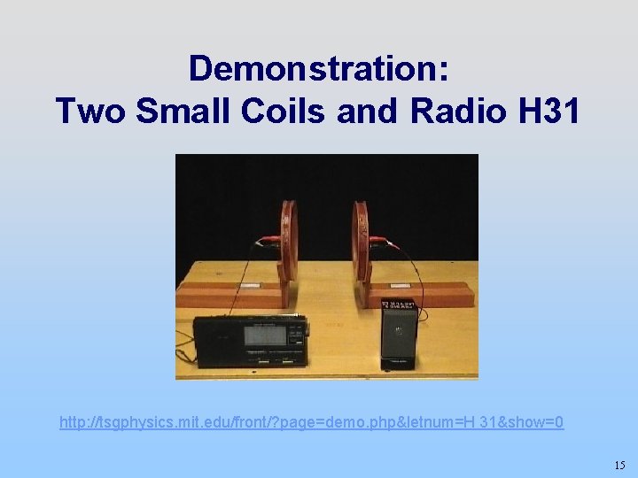
Demonstration: Two Small Coils and Radio H 31 http: //tsgphysics. mit. edu/front/? page=demo. php&letnum=H 31&show=0 15
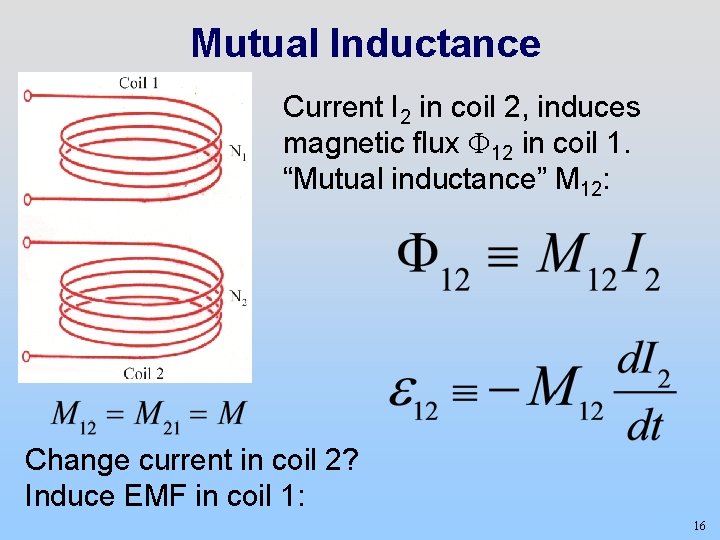
Mutual Inductance Current I 2 in coil 2, induces magnetic flux F 12 in coil 1. “Mutual inductance” M 12: Change current in coil 2? Induce EMF in coil 1: 16
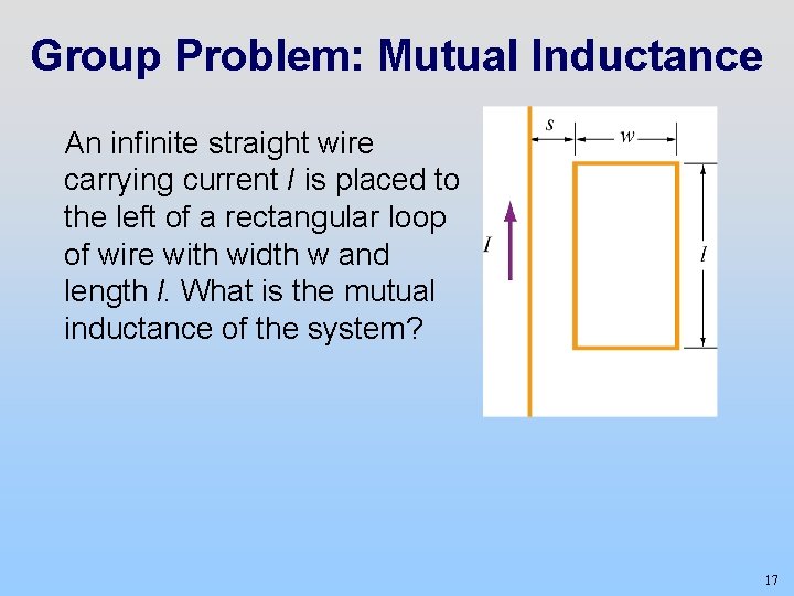
Group Problem: Mutual Inductance An infinite straight wire carrying current I is placed to the left of a rectangular loop of wire with width w and length l. What is the mutual inductance of the system? 17
Self Inductance 18
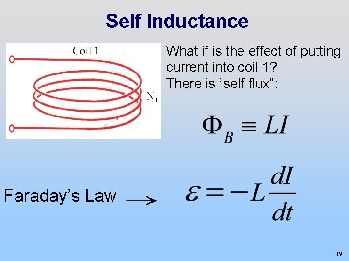
Self Inductance What if is the effect of putting current into coil 1? There is “self flux”: Faraday’s Law 19
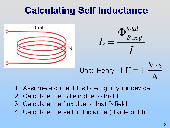
Calculating Self Inductance Unit: Henry 1. 2. 3. 4. Assume a current I is flowing in your device Calculate the B field due to that I Calculate the flux due to that B field Calculate the self inductance (divide out I) 20
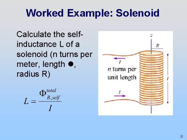
Worked Example: Solenoid Calculate the selfinductance L of a solenoid (n turns per meter, length , radius R) 21
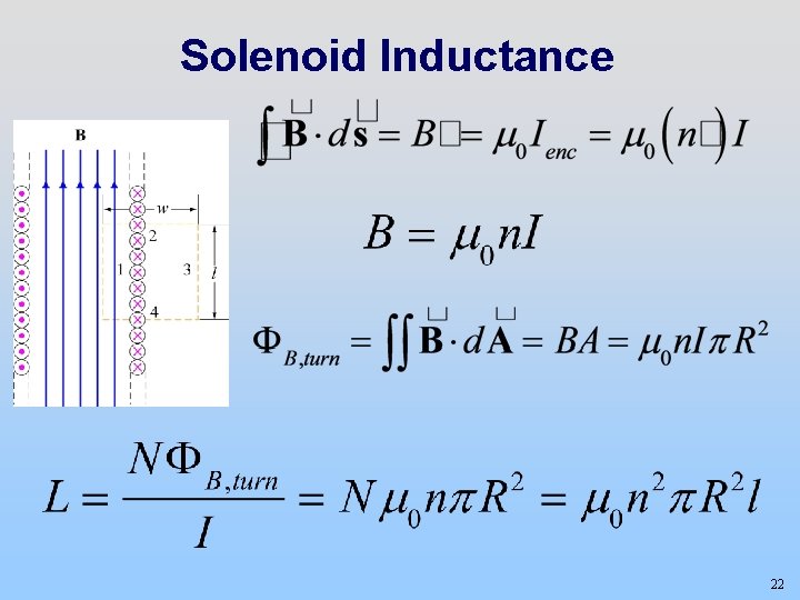
Solenoid Inductance 22
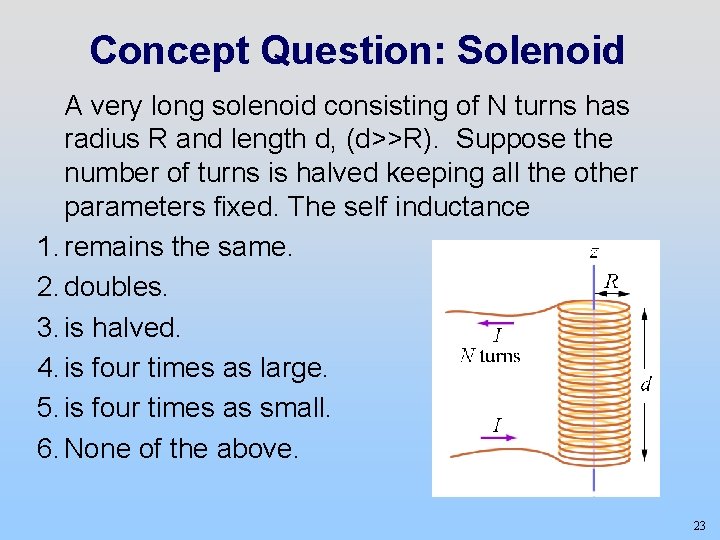
Concept Question: Solenoid A very long solenoid consisting of N turns has radius R and length d, (d>>R). Suppose the number of turns is halved keeping all the other parameters fixed. The self inductance 1. remains the same. 2. doubles. 3. is halved. 4. is four times as large. 5. is four times as small. 6. None of the above. 23
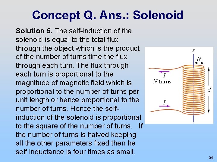
Concept Q. Ans. : Solenoid Solution 5. The self-induction of the solenoid is equal to the total flux through the object which is the product of the number of turns time the flux through each turn. The flux through each turn is proportional to the magnitude of magnetic field which is proportional to the number of turns per unit length or hence proportional to the number of turns. Hence the selfinduction of the solenoid is proportional to the square of the number of turns. If the number of turns is halved keeping all the other parameters fixed then he self inductance is four times as small. 24
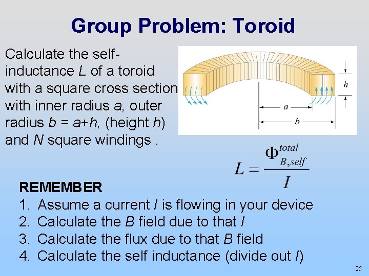
Group Problem: Toroid Calculate the selfinductance L of a toroid with a square cross section with inner radius a, outer radius b = a+h, (height h) and N square windings. REMEMBER 1. Assume a current I is flowing in your device 2. Calculate the B field due to that I 3. Calculate the flux due to that B field 4. Calculate the self inductance (divide out I) 25
Energy in Inductors 26
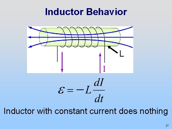
Inductor Behavior L I Inductor with constant current does nothing 27
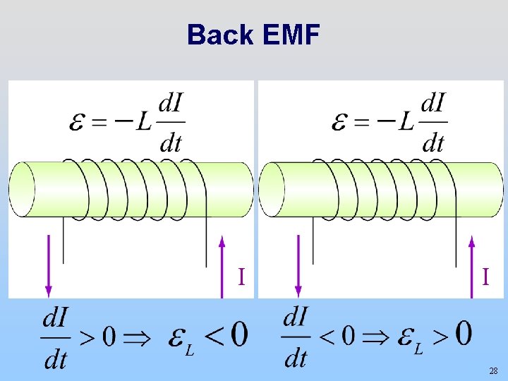
Back EMF I I 28
Demos: 26 -152 Back “emf” in Large http: //tsgphysics. mit. edu/front/? page=demo. php&letnum=H 17&show=0 Inductor H 17 32 -082 Marconi Coil H 12 http: //tsgphysics. mit. edu/front/? page=demo. php&letnum=H 12&show=0 29
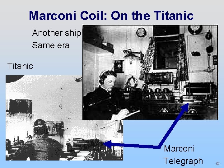
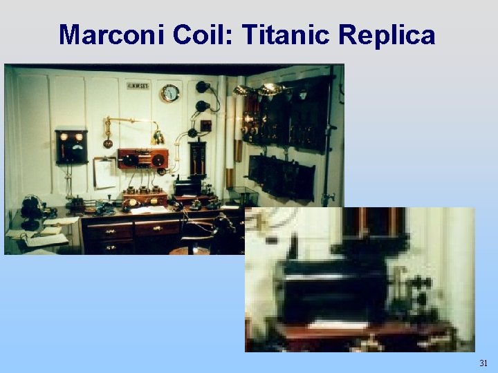
Marconi Coil: On the Titanic Another ship Same era Titanic Marconi Telegraph 30
Marconi Coil: Titanic Replica 31
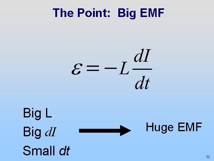
The Point: Big EMF Big L Big d. I Small dt Huge EMF 32
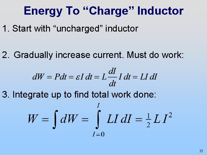
Energy To “Charge” Inductor 1. Start with “uncharged” inductor 2. Gradually increase current. Must do work: 3. Integrate up to find total work done: 33
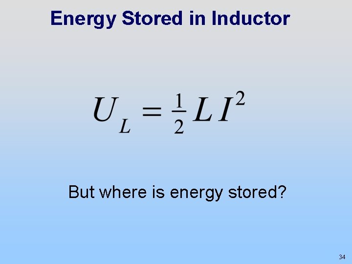
Energy Stored in Inductor But where is energy stored? 34
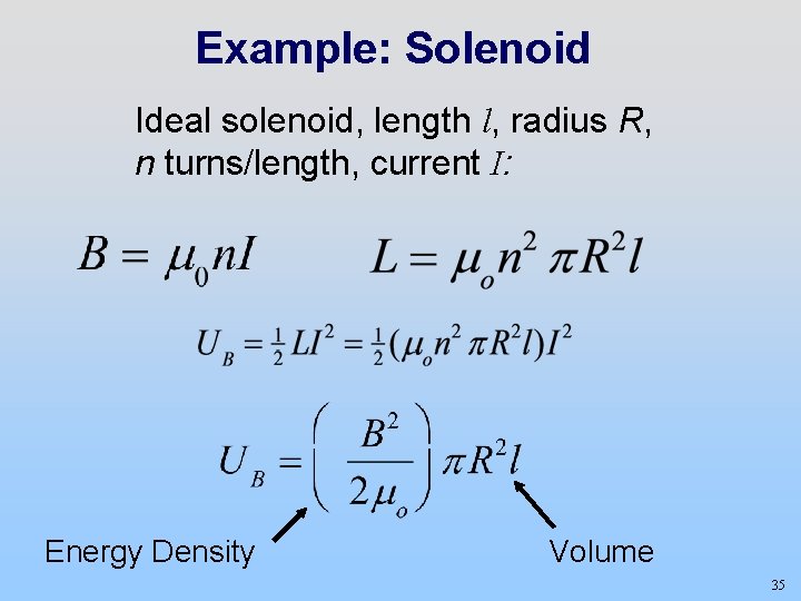
Example: Solenoid Ideal solenoid, length l, radius R, n turns/length, current I: Energy Density Volume 35
Energy Density Energy is stored in the magnetic field Magnetic Energy Density Energy is stored in the electric field Electric Energy Density 36
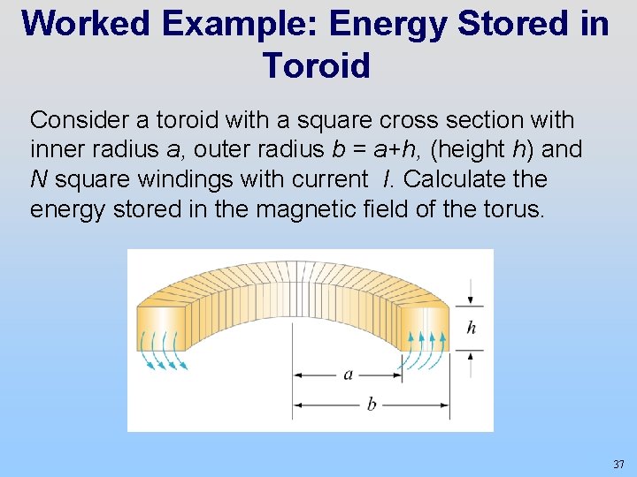
Worked Example: Energy Stored in Toroid Consider a toroid with a square cross section with inner radius a, outer radius b = a+h, (height h) and N square windings with current I. Calculate the energy stored in the magnetic field of the torus. 37
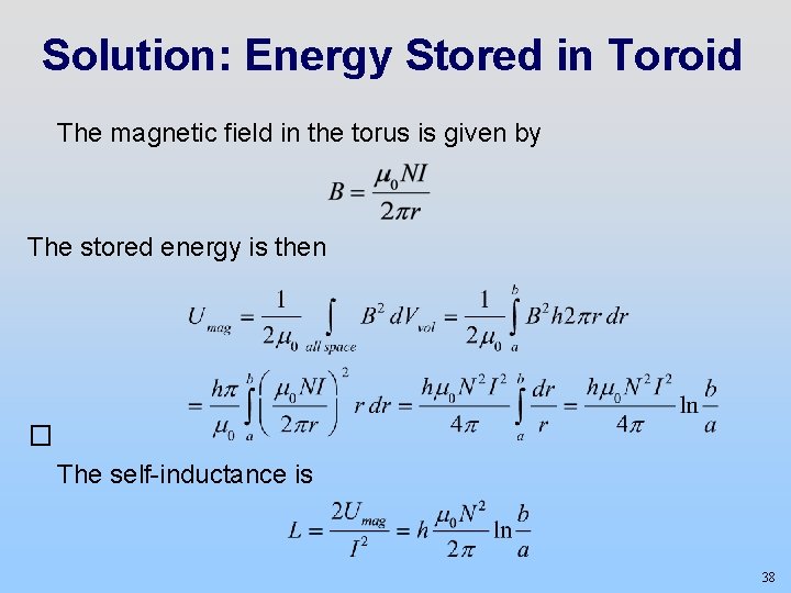
Solution: Energy Stored in Toroid The magnetic field in the torus is given by The stored energy is then � The self-inductance is 38
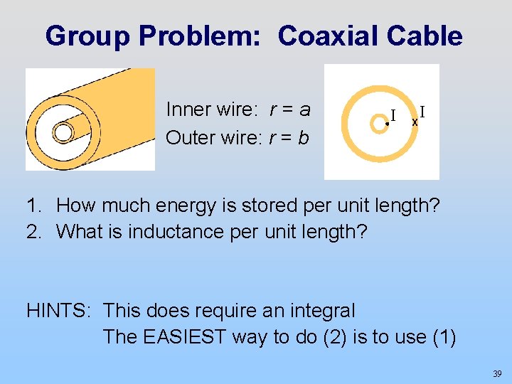
Group Problem: Coaxial Cable Inner wire: r = a Outer wire: r = b I X I 1. How much energy is stored per unit length? 2. What is inductance per unit length? HINTS: This does require an integral The EASIEST way to do (2) is to use (1) 39
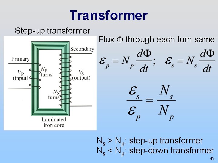
Transformer Step-up transformer Flux F through each turn same: Ns > Np: step-up transformer Ns < Np: step-down transformer 40
Demonstrations: 26 -152 One Turn Secondary: Nail H 10 http: //tsgphysics. mit. edu/front/? page=demo. php&letnum=H 10&show=0 26 -152 Many Turn Secondary: Jacob’s Ladder H 11 http: //tsgphysics. mit. edu/front/? page=demo. php&letnum=H 11&show=0 32 -082 Variable Turns Around a Primary Coil H 9 http: //tsgphysics. mit. edu/front/? page=demo. php&letnum=H 9&show=0 41
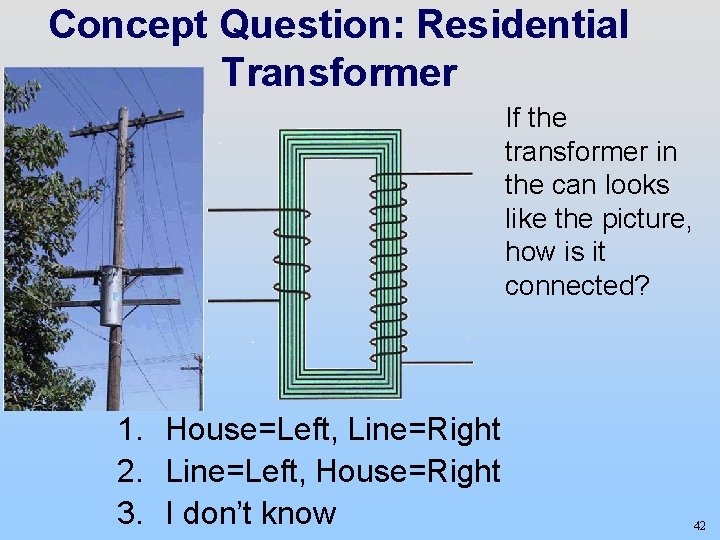
Concept Question: Residential Transformer If the transformer in the can looks like the picture, how is it connected? 1. House=Left, Line=Right 2. Line=Left, House=Right 3. I don’t know 42
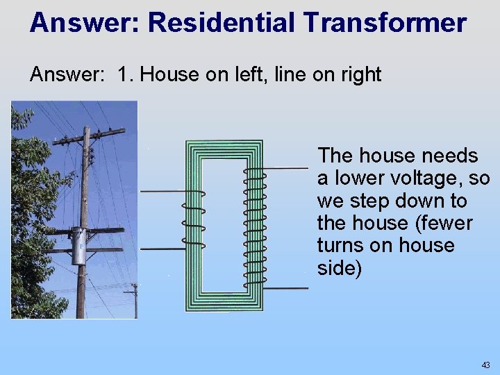
Answer: Residential Transformer Answer: 1. House on left, line on right The house needs a lower voltage, so we step down to the house (fewer turns on house side) 43
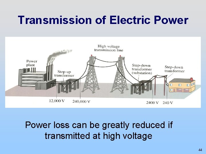
Transmission of Electric Power loss can be greatly reduced if transmitted at high voltage 44
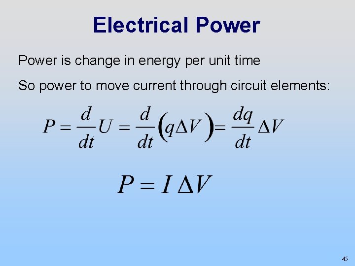
Electrical Power is change in energy per unit time So power to move current through circuit elements: 45
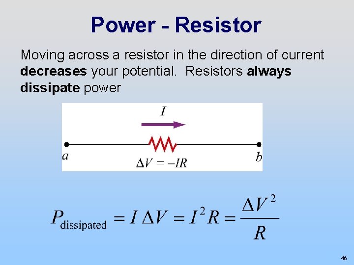
Power - Resistor Moving across a resistor in the direction of current decreases your potential. Resistors always dissipate power 46
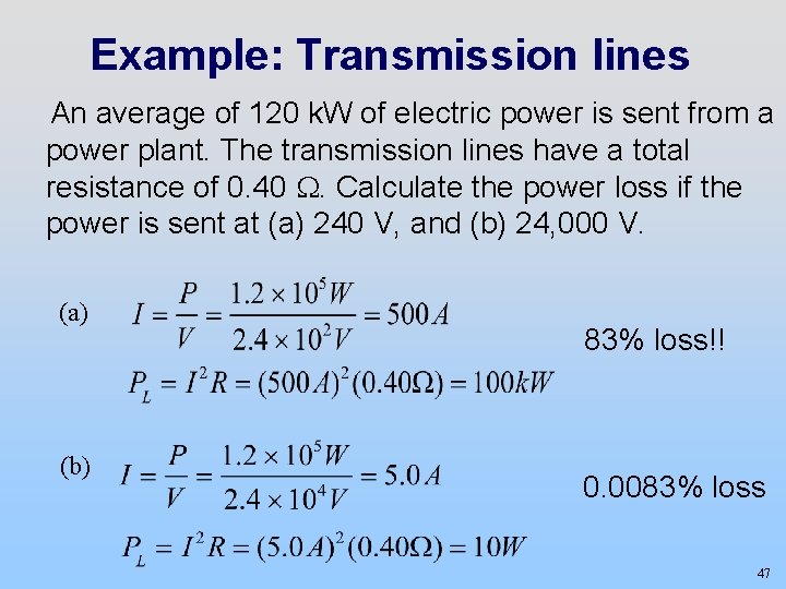
Example: Transmission lines An average of 120 k. W of electric power is sent from a power plant. The transmission lines have a total resistance of 0. 40 W. Calculate the power loss if the power is sent at (a) 240 V, and (b) 24, 000 V. (a) (b) 83% loss!! 0. 0083% loss 47
Transmission lines We just calculated that I 2 R is smaller for bigger voltages. What about V 2/R? Isn’t that bigger? Why doesn’t that matter? 48