CHAPTER 4 MAGNETIC PROPERTIES OF MATERIAL MDM HANA

")

 Basic Concept Electric Dipoles Magnetic Dipoles • Electric dipole (+ve & -ve")


 is produced by currentcarrying conductor.")
 with magnitude current")


 Magnetic Susceptibility • M is the induced magnetic moment per unit volume due")
 TYPES OF MAGNETISM Magnetic induction B (tesla) (3) ferromagnetic e. g. Fe")
 paramagnetic random aligned (3) ferromagnetic ferrimagnetic aligned opposing")
. DIAMAGNETISM opposing (1) diamagnetic Applied Magnetic Field (H) none No Applied Magnetic Field")
. PARAMAGNETISM Applied Magnetic Field (H) opposing (1) diamagnetic none No Applied Magnetic Field")


 ferromagnetic ferrimagnetic aligned (3). FERROMAGNETISM Ø Possess a permanent magnetic moment in")
 DOMAINS AND HYSTERESIS Schematic depiction of domains in a ferromagnetic or ferrimagnetic")

 increases, the domains that are")
 versus the magnetic field strength (H) for")


 SOFT VS HARD MAGNETS")


. •")


- Slides: 40
CHAPTER 4: MAGNETIC PROPERTIES OF MATERIAL MDM HANA ABDULL HALIM
Magnetic Resonance Imaging (MRI)
http: //www. youtube. com/watch? v=1 Euy. Z 5 Lml 4 k https: //www. youtube. com/watch? v=Om. Mu. Gr 0 UFbs
(4. 1) Basic Concept Electric Dipoles Magnetic Dipoles • Electric dipole (+ve & -ve charge). • Magnetic dipole (south & North).
Comparison Dielectric vs Magnetic
MAGNETIC FIELD Magnetic field lines of force around: • a current loop and • a bar magnet 8
MAGNETIC MOMENT
ORIGINS OF MAGNETIC MOMENTS • The macroscopic magnetic properties of materials are a consequence of magnetic moments associated with individual electrons. • Measures the response of electrons to a magnetic field. • Net magnetic moment: --sum of moments from all electrons. • Electrons produce magnetic moments: magnetic moments electron nucleus Orbital magnetic moment electron spin Spin magnetic moment
• The origin of atomic magnetic moments is the incomplete cancellation of electronic magnetic moments. • Electron spin and orbital motion both have magnetic moments associated with them. • If the cancellation of electronic moments is incomplete then the atom has a net magnetic moment. • But in most atoms the electronic moments are oriented so that they cancel giving no net atomic magnetic moment, leading to diamagnetism.
• The spin moment of an electron with spin up will cancel that of one with spin down. • Magnetic elements: Nickel, Chromium, iron, cobalt, manganese, and etc. • Thus materials composed of atoms having completely filled electron shells are not capable of being permanently magnetized. • This category includes the inert gases (He, Ne, Ar, etc. ) as well as some ionic materials.
MAGNETIC FIELD STRENGTH, H • Magnetic field strength (H) is produced by currentcarrying conductor. • Unit = Amp-turn/m • Magnetic Flux density (B) is new additive magnetic field once the bar inside solenoid get magnetized. • Unit = Tesla 13
• A cylindrical coil/solenoid consists of N turns, length (l) with magnitude current (I ) generate the magnetic field, then: • Magnetic field strength, H within a solenoid: H = applied magnetic field units = (ampere-turns/m). I = current. L = length of solenoid. N = number of turns. 14
Vacuum condition Non-Vacuum condition Magnetic flux density, μ = permeability (property of the specific medium). μo = permeability of vacuum (4π x 10 -7 H/m)
• μr is relative permeability. • μr of a material is a measure of the degree to which the material can be magnetized / or how ease the B field can be induced in the presence of an external H field. • μ is magnetic permeability. • μ is a measure of the increment on magnetization when a ferromagnetic material is placed in an applied magnetic field.
(Magnetization) Magnetic Susceptibility • M is the induced magnetic moment per unit volume due to the bar inside the solenoid.
(4. 2) TYPES OF MAGNETISM Magnetic induction B (tesla) (3) ferromagnetic e. g. Fe 3 O 4, Ni. Fe 2 O 4 ferrimagnetic e. g. ferrite( ), Co, Ni, Gd (c m as large as 10 6 ) (2) paramagnetic (cm ~ 10 -4) e. g. , Al, Cr, Mo, Na, Ti, Zr vacuum (c = 0) (1) diamagnetic ( c m ~ -10 -5 ) e. g. , Cu, Au, Si, Ag, Zn Strength of applied magnetic field (H) (ampere-turns/m) 18
MAGNETIC MOMENTS FOR 3 TYPES (2) paramagnetic random aligned (3) ferromagnetic ferrimagnetic aligned opposing Applied Magnetic Field (H) aligned (1) diamagnetic none No Applied Magnetic Field (H = 0) 19
(1). DIAMAGNETISM opposing (1) diamagnetic Applied Magnetic Field (H) none No Applied Magnetic Field (H = 0) - Weak magnetism that is non permanent dipoles and persist only while an external field applied. - Magnetic moment is extremely small, and in a direction opposite to that of the applied field. - Relative permeability (µr) is less than unity (vacuum). - Negative magnetic susceptibility (Xm).
(2). PARAMAGNETISM Applied Magnetic Field (H) opposing (1) diamagnetic none No Applied Magnetic Field (H = 0) - H = 0, each atomic dipole possesses a permanent dipole, randomly oriented. - while an external field applied, these atomic dipole preferentially align by rotation. - Relative permeability µr is greater than unity (vacuum). - relatively small, but Positive magnetic susceptibility.
DIAMAGNETISM AND PARAMAGNETISM • Schematic representation of the flux density B versus the magnetic field strength H for diamagnetic and paramagnetic materials. • Diamagnetism and paramagnetism materials are considers to non magnetic because they exhibit magnetization only when in the presence of an external field. 22
DIAMAGNETISM AND PARAMAGNETISM Room-Temperature Magnetic Susceptibilities for Diamagnetic and Paramagnetic Materials 23
aligned (3) ferromagnetic ferrimagnetic aligned (3). FERROMAGNETISM Ø Possess a permanent magnetic moment in the absence of an internal field due to electron spin – uncancelled electron spin and small contribution of orbital magnetic moment. Ø Manifest very large and permanent magnetization. Ø Magnetic susceptibilities is high.
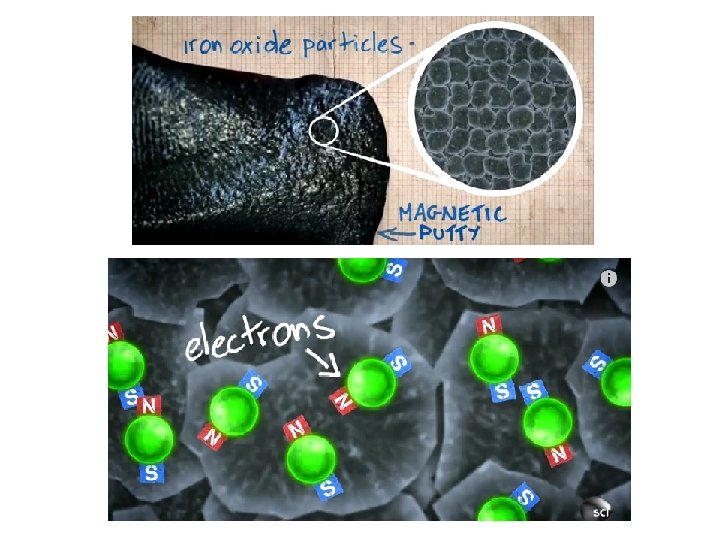
(4. 3) DOMAINS AND HYSTERESIS Schematic depiction of domains in a ferromagnetic or ferrimagnetic material. • Arrows represent atomic magnetic moment. • Within each domain, all dipoles are aligned, whereas the direction of alignment varies from one domain to another. 25
DOMAINS AND HYSTERESIS The gradual change in magnetic moment orientation across a domain wall 26
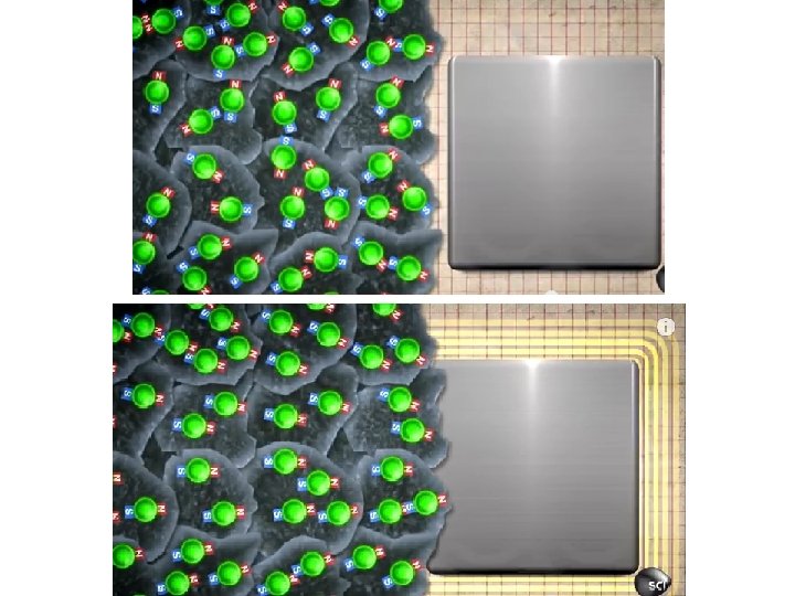
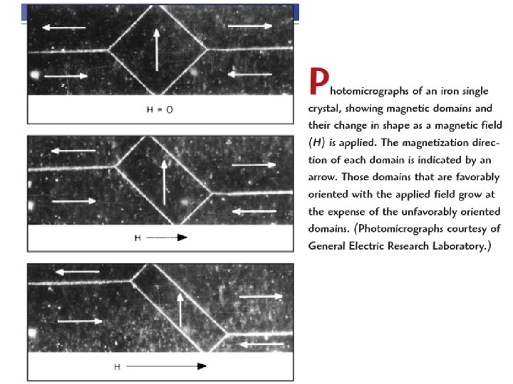
DOMAINS AND HYSTERESIS • As the applied field (H) increases, the domains that are oriented in directions favorable to (nearly aligned with) the H grow at expense of poorly oriented. Bsat H Magnetic induction (B) H H 0 • “Domains” with aligned magnetic moment grow at expense of poorly aligned ones! Applied Magnetic Field (H) H=0 27
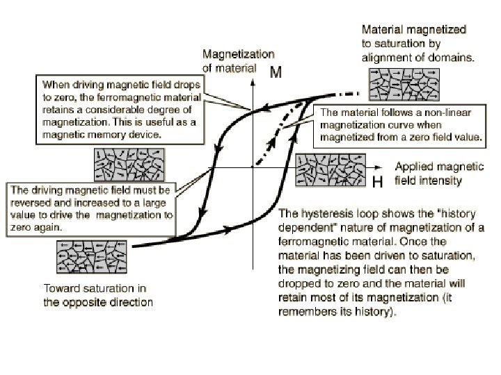
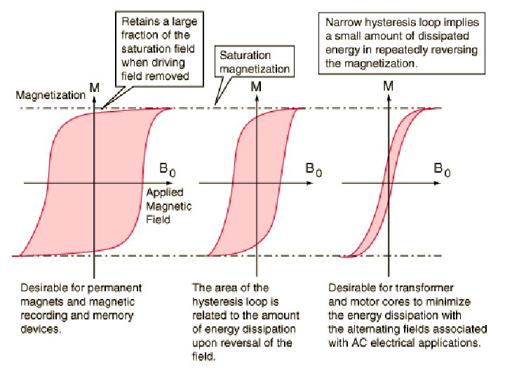
DOMAINS AND HYSTERESIS Magnetic flux density (B) versus the magnetic field strength (H) for a ferromagnetic material that is subjected to forward and reverse saturations (points S and S’). The hysteresis loop is represented by the solid red curve; the dashed blue curve indicates the initial magnetization. The remanence Br and the coercive force Hc are also shown. 29
DOMAINS AND HYSTERESIS • Hysteresis effect is produced in which the B fields lags behind the applied H field, or decreases at a lower rate. • At field H =0 (point R on the curve), there is a residual B field called the remanence or remanent flux density, Br. • At Br , the material remains magnetized in the absence of an external H field. 30
DOMAINS AND HYSTERESIS • To reduce the B field , an H field of magnitude Hc must be applied opposite to the original field; Hc = coercivity or coercive force. • Large coercivity, good for perm magnets -add particles/voids to make domain walls hard to move. • Small coercivity -- good for elec. Motors. 31
(4. 4) SOFT VS HARD MAGNETS
SOFT MAGNETS • Easily magnetized and demagnetized. • Free of structural defects, produce small coersive force (Hc). • Due to the easy movement of domain wall as the magnetic field change magnitude /direction. • High initial permeability (μ) • Low coercive (Hc). • Low hysteresis energy losses.
Ø Soft magnetic materials is easily magnetized and demagnetized. Ø Suitable used in devices that are subjected to alternating magnetic fields. Application: • Core for distribution power transformers. • Small electronic transformers • Stator and rotor materials for motors/ generators. • Dynamos, and switching circuits
HARD MAGNETS • Difficult demagnetized. • Has structural defects, produce large coercive (Hc). • Structural defects (particles of non-magnetic phase, voids in the magnetic material) tend to restrict the motion of domain walls, and thus increase the coersive (Hc). • Low initial permeability (μ). • High coercive (Hc). • High Remanence (Br ). • High hysteresis energy losses.
Ø Hard magnet is difficult demagnetized. Ø Suitable used for applications requiring permanent magnet Application: • Permanent magnet in laud speaker/ telephone receivers/ synchronous/ brushless motors/ automotive starting motors.
SUMMARY • A magnetic field can be produced by: -- putting a current through a coil. • Magnetic induction: -- occurs when a material is subjected to a magnetic field. -- is a change in magnetic moment from electrons. • Types of material response to a field are: -- ferri- or ferro-magnetic (large magnetic induction). -- paramagnetic (poor magnetic induction). -- diamagnetic (opposing magnetic moment). • Hard magnets: large coercivity. • Soft magnets: small coercivity. 38
MAGNETIC FIELD VECTORS Magnetic Units and Conversion Factors for the SI and cgs–emu Systems 40