Ultrafast Laser Driven Wakefield Accelerators Oleg Korovyanko 01122009


![Monoenergetic Beams from Literature Name Article Lab Energy d. E/E [Me. V] [%] Mangles](https://slidetodoc.com/presentation_image_h2/0e5d78b6dfb1ca51eabf21fa96ddcd92/image-13.jpg "Monoenergetic Beams from Literature Name Article Lab Energy d. E/E [Me. V] [%] Mangles")


 Cubic dispersion (gratings etc. ) Spectral Phase")
.")
")


 No significance Quadratic dispersion (glass etc.")
 • Suitable")


- Slides: 41
Ultrafast Laser -Driven Wakefield Accelerators Oleg Korovyanko 01/12/2009 SLAC AARD seminar
Outline Part 1: Wakefield accelerators: techniques to generate short e bunches Part 2: electron Production beams, of quality characterization and applications Part 3: Relevant laser techniques Part 4: Conclusion and perspectives
RF vs Plasma E-field max~ 10 Me. V /m E-field max~ 10 Ge. V/m Courtesy of V. Malka 1 m 100 mm RF cavity DWA Plasma cavity Diel. surface field breaks down @~ 10 Ge. V/m
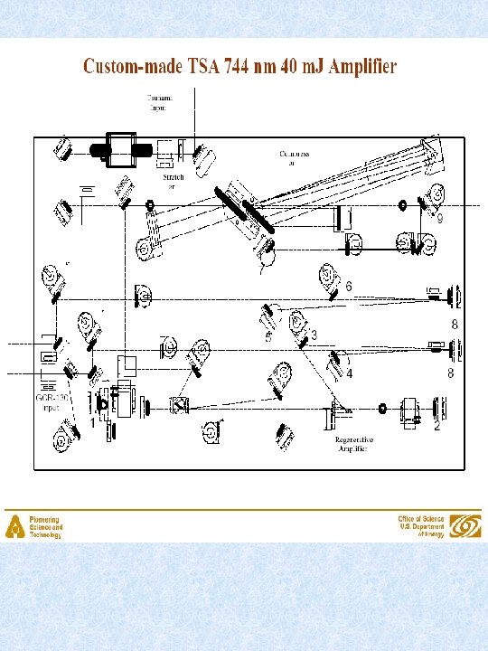
Argonne Wakefield Accelerator 1. 3 GHz, TSA 50
SHG 1 > 1. 6 W @ 400 nm SHG 2 FS D 1 IR 4 D 2 D 3 -4 WP SHGxtal THGxtal IR 2 -3 > 900 m. W @ 266 nm
ANL AWA 1. 3 GHz, TSA 50 • Built as DWA: witness, drive bunches • Two 248 nm pulses go to photocathode of RF gun, one or several drive bunches inter-pulse separation controlled w/ mechanical delay stage 23 cm, ~770 ps, or 10. 5 Lo, Lo=22 mm • A new UV stretcher utilizes thick BBO crystals in series • Laser mode at photocathode: adjustable iris at 1 m from photocathode
Escalations
Principle
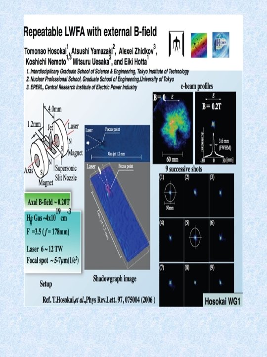
Monoenergetic Beams from Literature Name Article Lab Energy d. E/E [Me. V] [%] Mangles Nature (04) RAL t. L/Tp Charge Ne[p. C] Intensity 3 18 2 ] x 1018 /cm x 10 W/cm 73 6 22 20 2, 5 1, 6 Geddes Nature (04) L'OASIS 86 2 320 19 11 2, 2 Faure Nature (04) LOA 170 25 500 6 3 0, 7 9 0, 32 40 50 4, 6 336 40 Hidding PRL (2006) JETI 47 Hsieh IAMS 55 PRL (2006) 2, 6 Hosokai PRE (2006) U. Tokyo 11, 5 10 10 80 22 3, 0 Miura APL (2005) AIST 7 20 432 E-6 130 5 5, 1 Hafz PRE (2006) KERI 4, 3 93 200 28 1 33, 4 Mori Ar. Xiv (06) JAERI 20 24 0, 8 50 0, 9 4, 5 Lund LC 150 20 20 5 1, 4 Mangles PRL (2006) State-of-art gradient 27 Ge. V/m, SLAC, 27 Ge. V drive, Nature’ 2007
Towards longer interaction length Diffraction length L~pr 2/l 0 Rayleigh Dephasing length ~ a 0 lp 3/ l 0 2 Pump depletion length a 0 >>1 • Expanding Bubble Injection regime Degrades emittance due to high transverse field – control trapping Pre-formed channel injection : plasma “fiber” Optical injection by colliding pulse Capillary discharge channel
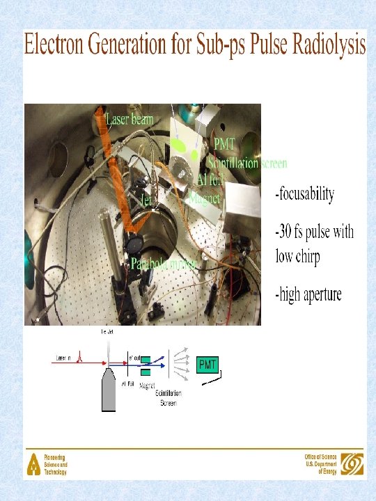
LOA Experimental set-up electron spectrometer LANEX B Field to shadowgraphy diagnostic Probe beam Gas jet Injection beam Pump beam 250 m. J, 30 fs ffwhm=30 µm I ~ 4× 10¹⁷ W/cm 2 a 1=0. 4 700 m. J, 30 fs, ffwhm=16 µm I ~ 3× 10¹⁸ W/cm 2 a 0=1. 2
LBNL Group
Laser plasma injector : Ge. V electron beams 18 -3 w 0 =20 mm t =30 fs P =200 TW l =0. 8 mm a 0 = 4 np =1. 5 × 10 cm � � f(E) (a. u. ) 2. 5 After 5 Zr / 7. 5 mm 2 1. 5 1 � � 0. 5 0 800 1200 1600 2000 Energy (Me. V) Courtesy of UCLA& Golp groups
Monoenergetic bunch comes from colliding pulses: polarization test Parallel polarization Crossed polarization
Is it Easy to Build?
No significance Quadratic dispersion (glass etc. ) Cubic dispersion (gratings etc. ) Spectral Phase
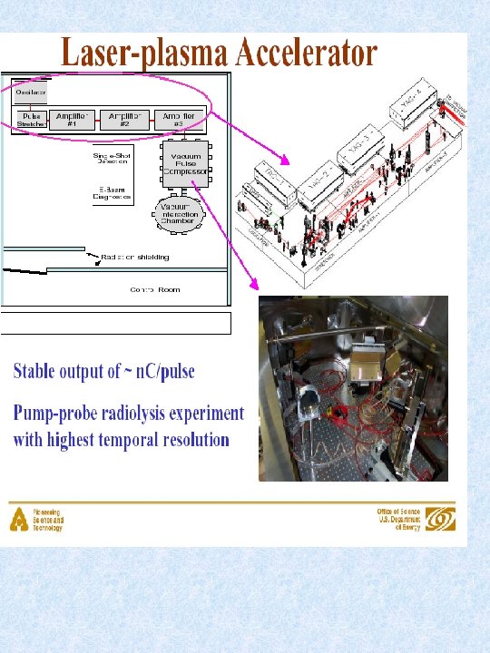
Water radiolysis D. A. Oulianov et al JAPS’ (2007).
• How to control injection? -inject electron beam from LINAC (SLAC, Nature’ 07) ANL LINAC Chuck Jonah, 1988 21 Me. V; 7 ps; 4 n. C; plasma density 4 -7 x 1010 cm-3 -use laser-based ionization DWA : “chirped” bunches, break down due to CCR multiphoton ionization • *control of laser PW, wavelength • How to control acceleration? -plasma density -channel guiding (LBNL) -colliding pulse (LOA)
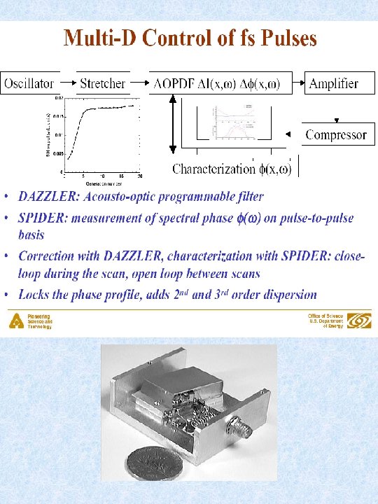
Acousto-optic shaping Dazzler - from Fastlite No need for zero dispersion stretcher Controls different dispersion orders
RGA pulse optimization test w/ SPIDER&Dazzler
Injection assisted by laser ionization • Laser-assisted ionization of atoms or ions • Two types: multiphoton and Frank-Keldysh tunneling • 13. 6 e. V vs 1. 5 e. V • DFG: Reducing laser frequency increases ponderomotive potential ~w-2 • HE TOPAS ~100 m. J @ l~9 mm
Laser techniques • Multi-bunch generation w/ DWA • Pulse shaping • DFG due to detuned from 800 synchronized Regen pulses • Atto-second science: CEP
Applications, Conclusions and Perspectives DW should be 7. 2 Ge. V with laser parameters (100 TW, a 0 ~3, Li~3. 8 cm) • THz source CCR • Hard X-ray fs source • X-ray free electron lasers • Radiology, biophysics around water window • Early stage of proton acceleration • 1 Te. V is a goal for HE physics is too far 32 k. J of laser energy (100 lasers of 300 J) • Optical Parametric CPA
• Efficiency • Emittance • Charge • Atto-second -ESASE
Thank you
Background. Parametric interaction wp = ws + wi phase matching conditions in a uniaxial x-stal such as BBO kp = ks + ki Non-collinear Each photon in idler beam generated together with a photon in signal beam S P I II P
PW Spectral Phase Cubic dispersion (gratings etc. ) No significance Quadratic dispersion (glass etc. )
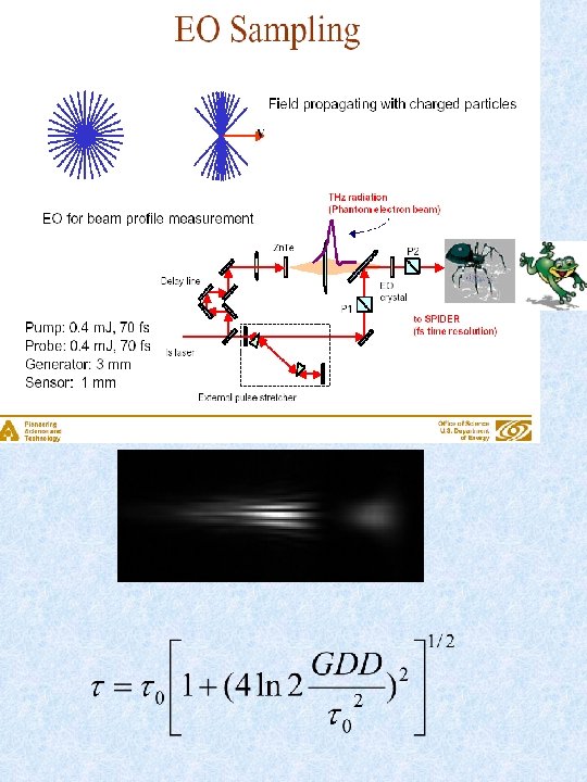
FROGs • Frequency Resolved Optical Gating (Kane and Trebino’ Opt Lett’ 1993) • Suitable for single-shot detection • Not an interferometric technique, just 2 D spectrogram of cross-correlation function • Not easy to reconstruct E(w, t): iterative algorithm, t-direction ambiguity • Slight modification (Masalov et al, JOSA 2001) makes use of spatial interferometry wavelength slit 2 nd harmonic Doubling x -stal t
Images
SPIDER c 2 2 p/t t~2 ps t w • Spectral phase interferometry for direct electric-field reconstruction (Iaconis and Walmsley, Opt Lett. ‘ 1998) • Spectral interferogram of two frequency-shifted up-converted pulses; no reference needed • Non-iterative reconstruction algorithm; 1 D data set
APE design
Pulse tilt
TFPA- pulse front inversion
KERI