Topology Optimization through Computer Aided Software 2018 ASPIRES


- Slides: 27
Topology Optimization through Computer Aided Software 2018 ASPIRES Summer Internship Program Final Program Presentation Yardley Ordonez Adrian Bituin Krystal Kyain Alec Maxwell; Wen Li Tang; Prof. Zhaoshuo Jiang
Outline § Background & Motivation § Proposed Solution § Results § Future Plans § Conclusion 2
Background – High-rise Structures 3
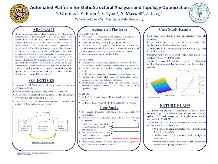
Background – High-rise Structures cont. § Solution for overpopulation § Efficient static structures § Iconic structures § Economical Design 4
Background – Topology Optimization § Optimize a given design with a set of constraints § Create a cost effective design with increased performance • Maintain highest stiffness with least amount of material 5
Background – Finite Element Method § Break down design into finite number of smaller elements Element § Each element connected by nodes § Purpose of a mesh Node § Apply loads at certain nodes 6
Why Automate? Geometry Optimization Engine Structural Solver Graphical User Interface § Analyses performed through GUI is extremely tedious and labor-intensive Results 8
Sequence Flowchart MATLAB Script 1. 2. Auto. CAD/Auto. LISP 3. ANSYS APDL Geometry & Loading Optimization & Creation Performance Evaluation MATLAB Results Extraction Next Candidate 4. § MATLAB will be used to guide the automation 9
Sequence Flowchart MATLAB Script Auto. CAD/Auto. LISP ANSYS APDL Geometry & Loading Optimization & Creation Performance Evaluation MATLAB Results Extraction Next Candidate § MATLAB will be used to guide the automation 10
Platform Sequence – Auto. LISP § Auto. CAD’s programming language • Create custom command to complete desired task § Be able to alter parameters easily § Automate the process of creating model and exporting . IGES file 11
Sequence Flowchart MATLAB Script Auto. CAD/Auto. LISP ANSYS APDL Geometry & Loading Optimization & Creation Performance Evaluation MATLAB Results Extraction Next Candidate § MATLAB will be used to guide the automation 12
Platform Sequence – APDL Scripting § Ansys Parametric Design Language: ANSYS Scripting Language § Write script to import model, apply a mesh, define load cases, perform topology optimization, and output results. § Ability to edit parameters quickly and easily. Input APDL Code 13
Platform Sequence – Sequence Flowchart MATLAB Script Auto. CAD/Auto. LISP ANSYS APDL Geometry & Loading Optimization & Creation Performance Evaluation MATLAB Results Extraction Next Candidate § MATLAB will be used to guide the automation 14
Platform Sequence – MATLAB § MATLAB code will: § Run Auto. LISP file through Auto. CAD and export into. IGES § Run APDL script file through ANSYS in the background. § Interpret and graph results. 15
Platform Execution– Geometry § Simple cantilever beam designed with Auto. LISP § Dimensions: 500 x 50 x 100 mm § Imported as. IGES file into ANSYS APDL 100 mm 500 mm 16
Platform Execution – APDL Scripting § APDL script will generate a mesh for the beam and will loop to vary the beam's mesh size four more times. § With each mesh iteration, the program will loop ten times, applying a point-load force at ten equally spaced x-locations along the top face of the beam. Fixed Support X = 0 mm X = 500 mm 17
Platform Execution– APDL Scripting X = 450 mm X = 500 mm (Continue incrementing by -50 mm) . . . § When force iterations are completed from 500 mm to 10 mm, begin again with new mesh size X = 50 mm 19
Platform Execution– APDL Scripting § The platform will then run a topology optimization analysis. 10 mm Mesh Size, 50% volume retained 20
Platform Execution– MATLAB § Read and compare force location, mesh size, and beam displacement results. § Large mesh sizes overestimate the beam's displacement, and converge to an equal value as it gets smaller 21
Platform Execution – MATLAB § Effect of mesh size on displacement not visually observable between small increments of size. 22
Point Load on Cantilever Beam § Displacement equation: compare experimental results vs. theoretical values. 23
Results Comparison to Theoretical Value § As illustrated, solution is more accurate with a smaller mesh size. 24
Future Plans § Current platform: Automated routine of performing analyses on a simple cantilever beam and outputting displacement results. § Prospective modifications with platform: o Shape optimization. o Analyze complex models. o Export different quantitative results. 25
Conclusion • New programming methods • Topology optimization • Teamwork • Time management 26
Questions? 27
Resources Some of the figures were accessed from the internet. The copyrights of the figures belong to the original authors. 28