The SPES layout construction and commissioning strategy A

- Slides: 43
The SPES layout, construction and commissioning strategy A. Pisent, L. Bellan, M. Comunian, INFN-LNL, Legnaro, Italy B. Chalykh, ITEP, Moscow, Russia A. Russo, L. Calabretta, INFN-LNS, Catania, Italy Thanks to SPES Team: G. Prete, G. Bisoffi, E. Fagotti, P. Favaron, A. Andrighetto, A. Pisent, M. Comunian, A. Palmieri, A. Porcellato, D. Zafiropoulos, L. Sarchiapone, J. Esposito, C. Roncolato, L. Ferrari, M. Rossignoli, M. Calderolla, M. Poggi, M. Manzolaro, J. Vasquez, M. Monetti, L. Calabretta, A. Russo, M. Guerzoni SPES, acronym of Selective Production of Exotic Species, is a CW radioactive ion beam facility under construction at LNL INFN in Italy.
Outline • Functional elements of SPES post-acceleration • The lay out. – New transfer line to experiment operational – Transport line from CB to ALPI main elements under procurement. – The new RFQ as new ALPI LINAC injector (mechanical design going on). • Transport line 1+ design to be frozen soon: – Low energy transport and selection; – RFQ cooler – High Resolution Mass Spectrometer; • ALPI LINAC for SPES. • Installation and beam commissioning sequence for the post accelerator.
Computational approach • The post acceleration of SPES requires extremely good magnetic selection, high transmission (precious beam) and very good knwoledge of the position, of amount and location of beam losses • The approach, computational tools (TRACEWIN, 10^5 macroparticles, accurate field maps. . ) are almost the same as for high intensity linacs (IFMIF or ESS) • 3° order matrix transport for separators optimization (GIOS). • 3 D field simulations with COMSOL and OPERA 3 D for field map calculation. • Sistematic error studies with massive computing parallelization….
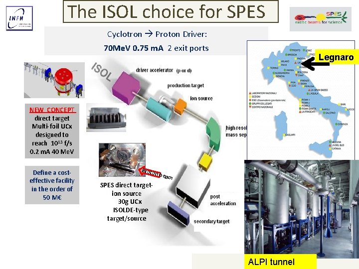
The ISOL choice for SPES Cyclotron Proton Driver: 70 Me. V 0. 75 m. A 2 exit ports Legnaro NEW CONCEPT direct target Multi-foil UCx designed to reach 1013 f/s 0. 2 m. A 40 Me. V Define a costeffective facility in the order of 50 M€ Proto n bea m SPES direct targetion source 30 g UCx ISOLDE-type target/source ALPI SC LINAC ALPI tunnel
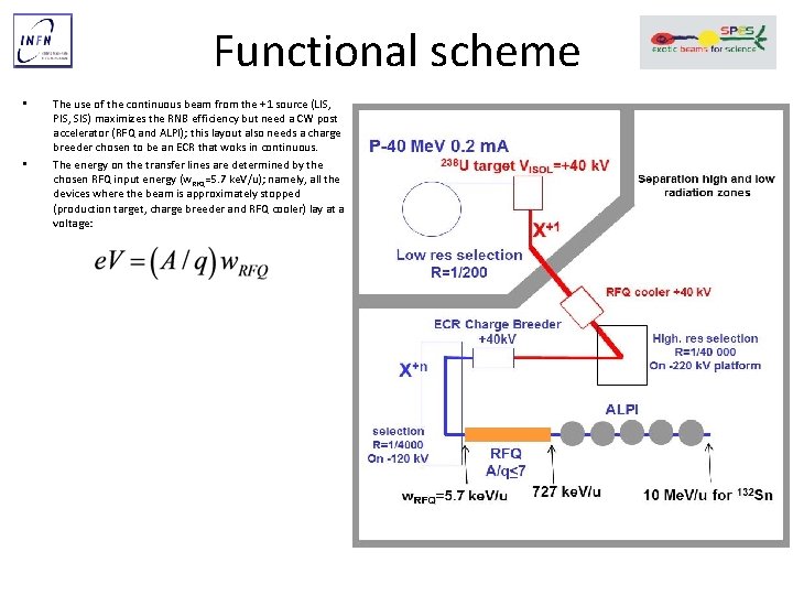
Functional scheme • • The use of the continuous beam from the +1 source (LIS, PIS, SIS) maximizes the RNB efficiency but need a CW post accelerator (RFQ and ALPI); this layout also needs a charge breeder chosen to be an ECR that woks in continuous. The energy on the transfer lines are determined by the chosen RFQ input energy (w. RFQ=5. 7 ke. V/u); namely, all the devices where the beam is approximately stopped (production target, charge breeder and RFQ cooler) lay at a voltage:
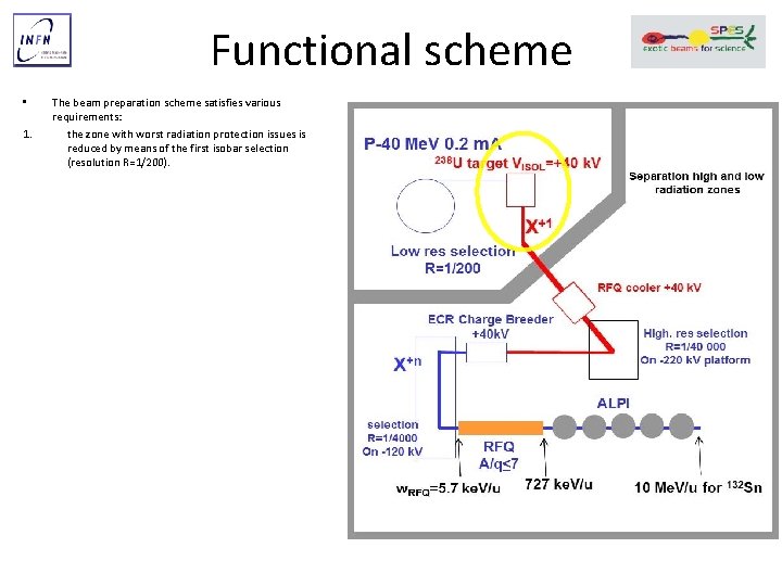
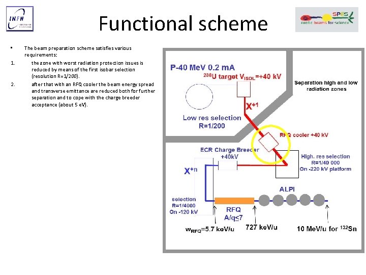
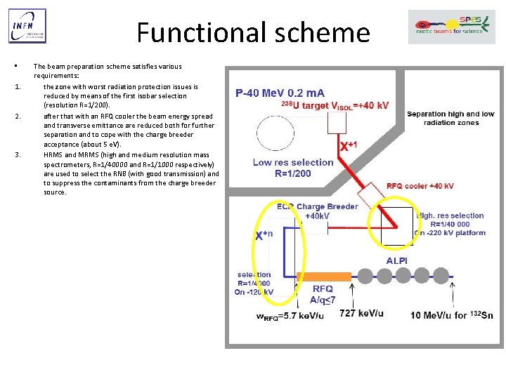
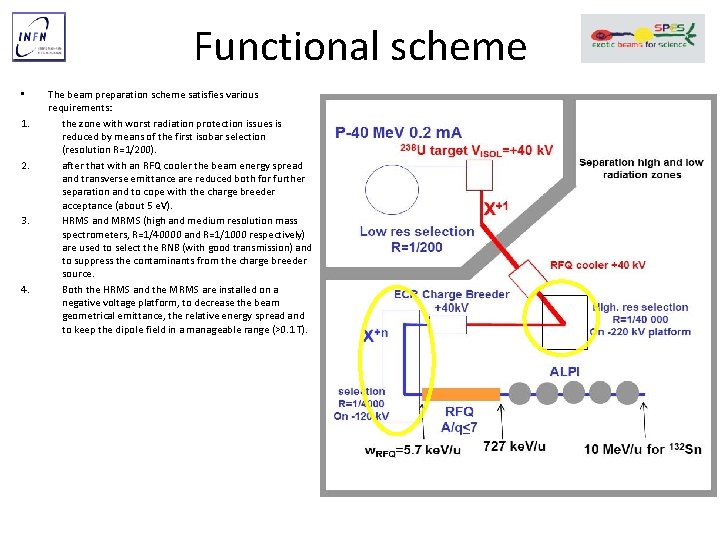
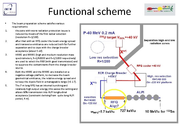
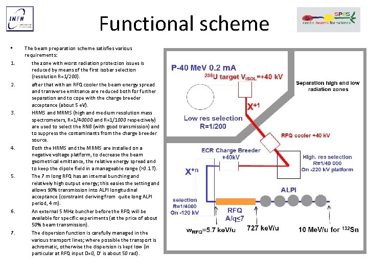
Functional scheme • 1. 2. 3. 4. 5. 6. 7. The beam preparation scheme satisfies various requirements: the zone with worst radiation protection issues is reduced by means of the first isobar selection (resolution R=1/200). after that with an RFQ cooler the beam energy spread and transverse emittance are reduced both for further separation and to cope with the charge breeder acceptance (about 5 e. V). HRMS and MRMS (high and medium resolution mass spectrometers, R=1/40000 and R=1/1000 respectively) are used to select the RNB (with good transmission) and to suppress the contaminants from the charge breeder source. Both the HRMS and the MRMS are installed on a negative voltage platform, to decrease the beam geometrical emittance, the relative energy spread and to keep the dipole field in a manageable range (>0. 1 T). The 7 m long RFQ has an internal bunching and relatively high output energy; this easies the setting and allows 90% transmission into ALPI longitudinal acceptance (constraint deriving from quite long ALPI period, 4 m). An external 5 MHz buncher before the RFQ will be available for specific experiments (at the price of about 50% beam transmission). The dispersion function is carefully managed in the various transport lines; where possible the transport is achromatic, otherwise the dispersion is kept low (in particular at RFQ input D=0, D’ is about 50 rad).
Functional scheme • 1. 2. 3. 4. 5. 6. 7. The beam preparation scheme satisfies various requirements: the zone with worst radiation protection issues is reduced by means of the first isobar selection (resolution R=1/200). after that with an RFQ cooler the beam energy spread and transverse emittance are reduced both for further separation and to cope with the charge breeder acceptance (about 5 e. V). HRMS and MRMS (high and medium resolution mass spectrometers, R=1/40000 and R=1/1000 respectively) are used to select the RNB (with good transmission) and to suppress the contaminants from the charge breeder source. Both the HRMS and the MRMS are installed on a negative voltage platform, to decrease the beam geometrical emittance, the relative energy spread and to keep the dipole field in a manageable range (>0. 1 T). The 7 m long RFQ has an internal bunching and relatively high output energy; this easies the setting and allows 90% transmission into ALPI longitudinal acceptance (constraint deriving from quite long ALPI period, 4 m). An external 5 MHz buncher before the RFQ will be available for specific experiments (at the price of about 50% beam transmission). The dispersion function is carefully managed in the various transport lines; where possible the transport is achromatic, otherwise the dispersion is kept low (in particular at RFQ input D=0, D’ is about 50 rad).
Functional scheme • 1. 2. 3. 4. 5. 6. 7. The beam preparation scheme satisfies various requirements: the zone with worst radiation protection issues is reduced by means of the first isobar selection (resolution R=1/200). after that with an RFQ cooler the beam energy spread and transverse emittance are reduced both for further separation and to cope with the charge breeder acceptance (about 5 e. V). HRMS and MRMS (high and medium resolution mass spectrometers, R=1/40000 and R=1/1000 respectively) are used to select the RNB (with good transmission) and to suppress the contaminants from the charge breeder source. Both the HRMS and the MRMS are installed on a negative voltage platform, to decrease the beam geometrical emittance, the relative energy spread and to keep the dipole field in a manageable range (>0. 1 T). The 7 m long RFQ has an internal bunching and relatively high output energy; this easies the setting and allows 90% transmission into ALPI longitudinal acceptance (constraint deriving from quite long ALPI period, 4 m). An external 5 MHz buncher before the RFQ will be available for specific experiments (at the price of about 50% beam transmission). The dispersion function is carefully managed in the various transport lines; where possible the transport is achromatic, otherwise the dispersion is kept low (in particular at RFQ input D=0, D’ is about 50 rad).
Functional scheme • 1. 2. 3. 4. 5. 6. 7. The beam preparation scheme satisfies various requirements: the zone with worst radiation protection issues is reduced by means of the first isobar selection (resolution R=1/200). after that with an RFQ cooler the beam energy spread and transverse emittance are reduced both for further separation and to cope with the charge breeder acceptance (about 5 e. V). HRMS and MRMS (high and medium resolution mass spectrometers, R=1/40000 and R=1/1000 respectively) are used to select the RNB (with good transmission) and to suppress the contaminants from the charge breeder source. Both the HRMS and the MRMS are installed on a negative voltage platform, to decrease the beam geometrical emittance, the relative energy spread and to keep the dipole field in a manageable range (>0. 1 T). The 7 m long RFQ has an internal bunching and relatively high output energy; this easies the setting and allows 90% transmission into ALPI longitudinal acceptance (constraint deriving from quite long ALPI period, 4 m). An external 5 MHz buncher before the RFQ will be available for specific experiments (at the price of about 50% beam transmission). The dispersion function is carefully managed in the various transport lines; where possible the transport is achromatic, otherwise the dispersion is kept low (in particular at RFQ input D=0, D’ is about 50 rad).
Functional scheme • 1. 2. 3. 4. 5. 6. 7. The beam preparation scheme satisfies various requirements: the zone with worst radiation protection issues is reduced by means of the first isobar selection (resolution R=1/200). after that with an RFQ cooler the beam energy spread and transverse emittance are reduced both for further separation and to cope with the charge breeder acceptance (about 5 e. V). HRMS and MRMS (high and medium resolution mass spectrometers, R=1/40000 and R=1/1000 respectively) are used to select the RNB (with good transmission) and to suppress the contaminants from the charge breeder source. Both the HRMS and the MRMS are installed on a negative voltage platform, to decrease the beam geometrical emittance, the relative energy spread and to keep the dipole field in a manageable range (>0. 1 T). The 7 m long RFQ has an internal bunching and relatively high output energy; this easies the setting and allows 90% transmission into ALPI longitudinal acceptance (constraint deriving from quite long ALPI period, 4 m). An external 5 MHz buncher before the RFQ will be available for specific experiments (at the price of about 50% beam transmission). The dispersion function is carefully managed in the various transport lines; where possible the transport is achromatic, otherwise the dispersion is kept low (in particular at RFQ input D=0, D’ is about 50 rad).
Functional scheme • 1. 2. 3. 4. 5. 6. 7. The beam preparation scheme satisfies various requirements: the zone with worst radiation protection issues is reduced by means of the first isobar selection (resolution R=1/200). after that with an RFQ cooler the beam energy spread and transverse emittance are reduced both for further separation and to cope with the charge breeder acceptance (about 5 e. V). HRMS and MRMS (high and medium resolution mass spectrometers, R=1/40000 and R=1/1000 respectively) are used to select the RNB (with good transmission) and to suppress the contaminants from the charge breeder source. Both the HRMS and the MRMS are installed on a negative voltage platform, to decrease the beam geometrical emittance, the relative energy spread and to keep the dipole field in a manageable range (>0. 1 T). The 7 m long RFQ has an internal bunching and relatively high output energy; this easies the setting and allows 90% transmission into ALPI longitudinal acceptance (constraint deriving from quite long ALPI period, 4 m). An external 5 MHz buncher before the RFQ will be available for specific experiments (at the price of about 50% beam transmission). The dispersion function is carefully managed in the various transport lines; where possible the transport is achromatic, otherwise the dispersion is kept low (in particular at RFQ input D=0, D’ is about 50 rad).
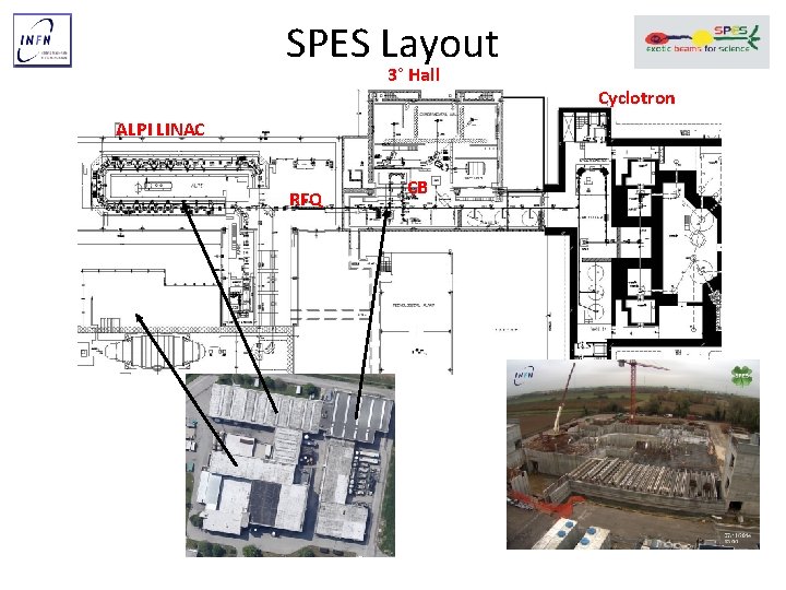
SPES Layout 3° Hall ALPI LINAC RFQ CB Cyclotron
Key technologies and choices • Vacuum (long lines <10 -8 mbar), reliable control of residual gasses. • Brazing (RFQ, bunchers…. ) • Optics elements: – Electrostatic quads when possible (but we have to rescale with A/q) – Magnetic dipoles for momentum analysis and dispersion control – Magnetic lenses (solenoids and quads) for the line MMRMS RFQ with possible energy upgrade (low energy high charge state) • Beam instrumentation for pilot beam, for low intensity (104 pps) and few tape station for species characterization
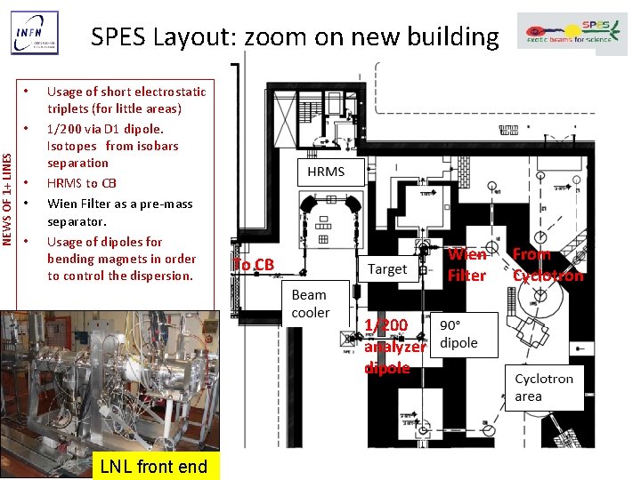
NEWS OF 1+ LINES SPES Layout: zoom on new building • • • Usage of short electrostatic triplets (for little areas) 1/200 via D 1 dipole. Isotopes from isobars separation HRMS to CB Wien Filter as a pre-mass separator. Usage of dipoles for bending magnets in order to control the dispersion. Wien Filter To CB 1/200 analyzer dipole LNL front end From Cyclotron
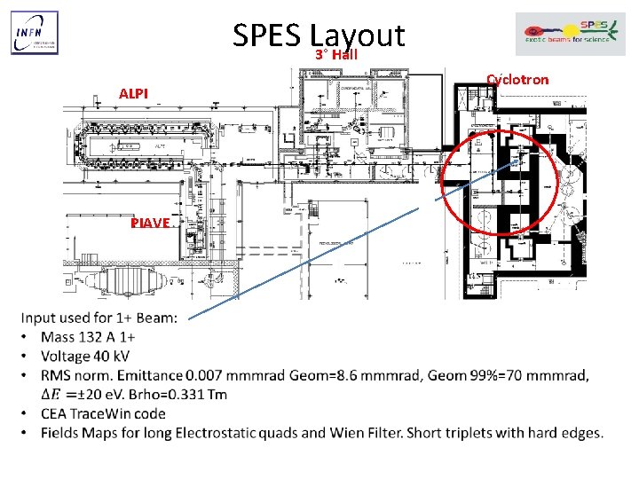
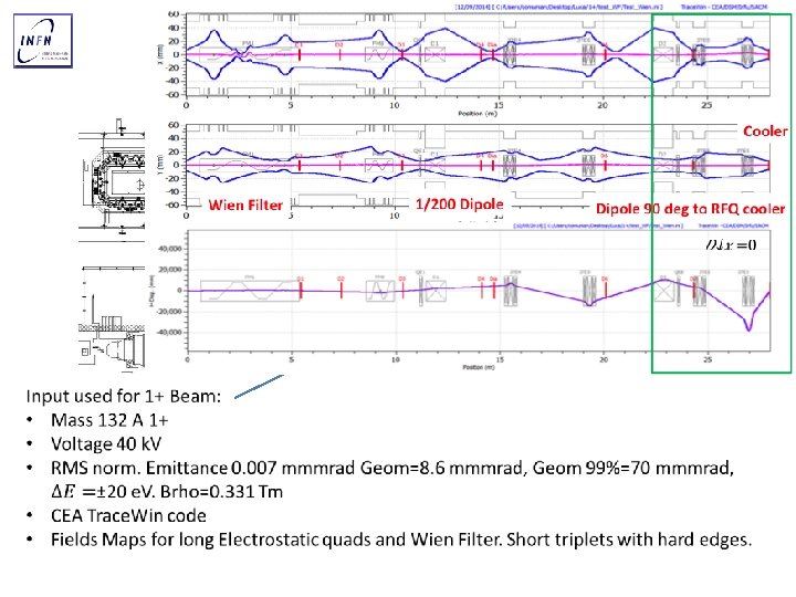
SPES Layout 3° Hall ALPI PIAVE Cyclotron
SPES Layout 3° Hall ALPI PIAVE Cyclotron
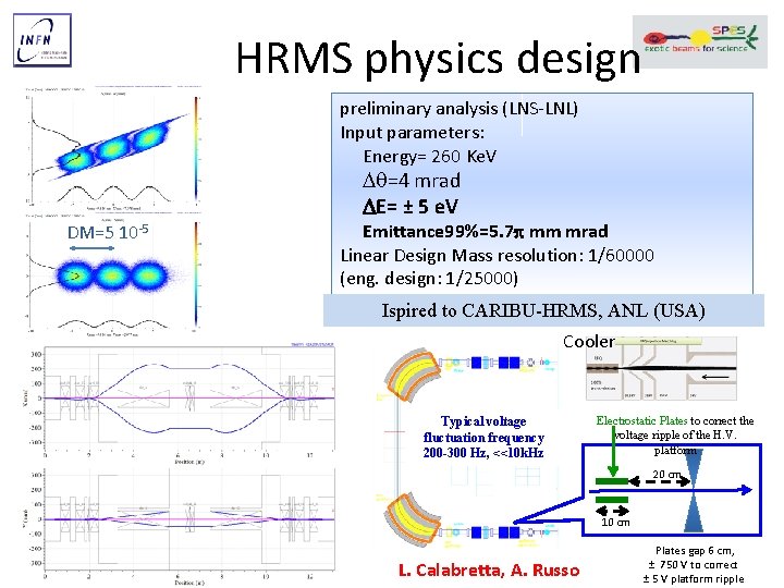
HRMS physics design preliminary analysis (LNS-LNL) Input parameters: Energy= 260 Ke. V D =4 mrad DE= ± 5 e. V DM=5 10 -5 Emittance 99%=5. 7 p mm mrad Linear Design Mass resolution: 1/60000 (eng. design: 1/25000) Ispired to CARIBU-HRMS, ANL (USA) Cooler Typical voltage fluctuation frequency 200 -300 Hz, <<10 k. Hz Electrostatic Plates to correct the voltage ripple of the H. V. platform 20 cm 10 cm L. Calabretta, A. Russo Plates gap 6 cm, ± 750 V to correct ± 5 V platform ripple
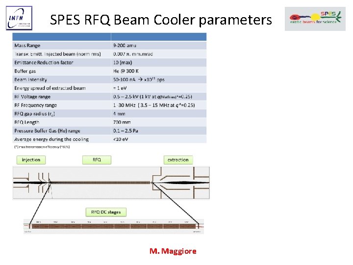
SPES RFQ Beam Cooler parameters M. Maggiore
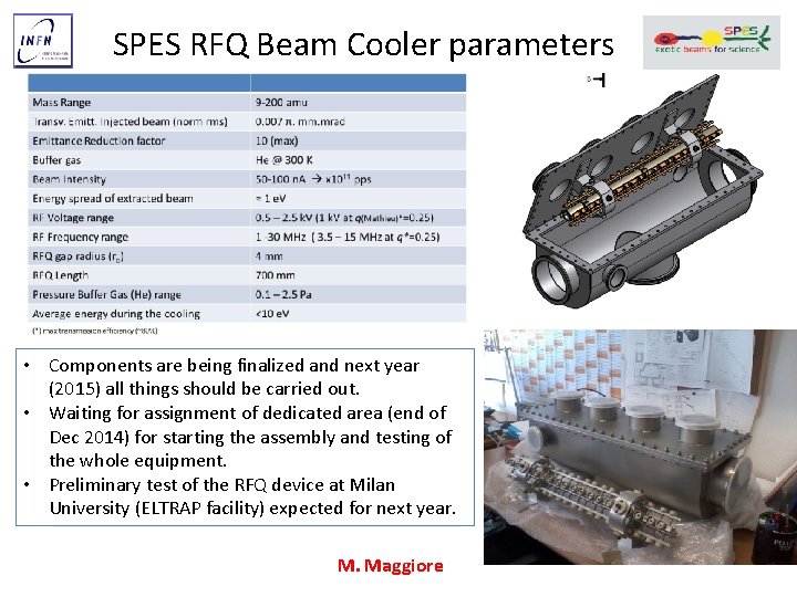
SPES RFQ Beam Cooler parameters • Components are being finalized and next year (2015) all things should be carried out. • Waiting for assignment of dedicated area (end of Dec 2014) for starting the assembly and testing of the whole equipment. • Preliminary test of the RFQ device at Milan University (ELTRAP facility) expected for next year. M. Maggiore
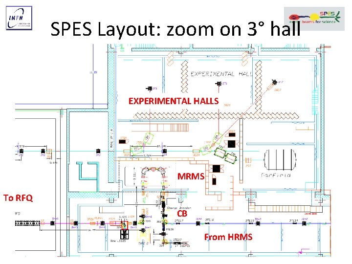
SPES Layout: zoom on 3° hall EXPERIMENTAL HALLS MRMS To RFQ CB From HRMS
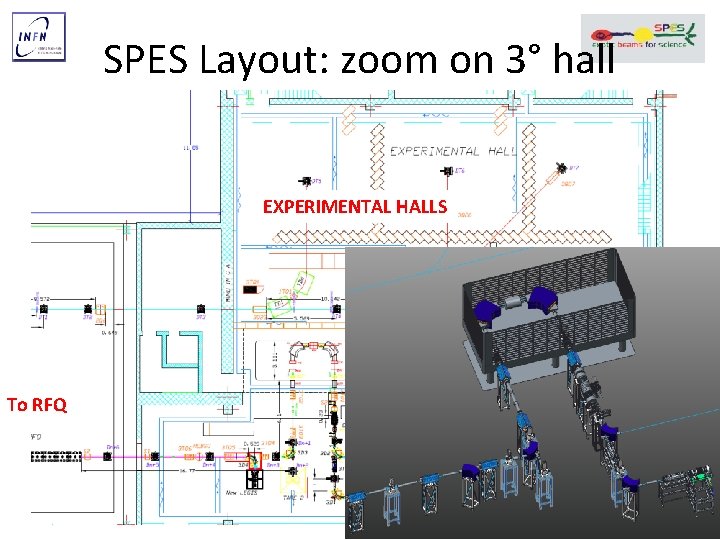
SPES Layout: zoom on 3° hall EXPERIMENTAL HALLS MRMS To RFQ CB From HRMS
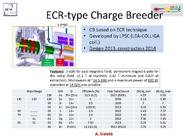
ECR-type Charge Breeder • CB based on ECR technique • Developed by LPSC (LEA-COLLIGA coll. ) • Design 2013, construction 2014 130 90 74 90 Mass Range 132 ………. . 81 91 138 134 98 94 99 80 82 92 34 ION Q Xe 20+ (21+) Sn 21+ Sr 14+ Kr 16+(18+) Y 14+ Zn 10+ Ga 11+ Rb 17+ Ar 8+(9+) Efficiency [%] 10, 9 (6, 2) 6 3. 5 12(8, 5) 3. 3 2. 8 2 7. 50 16, 2(11, 5) Year Data Source 2012 (2005) 2005 2013 2002 2013 2012 (2013) A. Galatà (M/q)_min 6. 57 6. 19 7 5. 22 6. 43 7. 40 7. 36 5. 29 3. 78 (M/q)_max 6. 90 6. 38 7 5. 88 7. 07 8. 00 7. 45 5. 41 4. 25
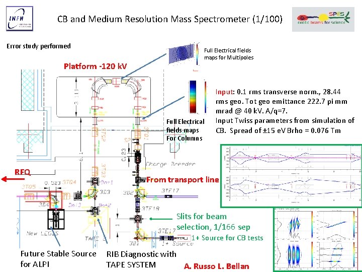
CB and Medium Resolution Mass Spectrometer (1/100) Error study performed Platform -120 k. V Full Electrical fields maps for Multipoles Full Electrical fields maps For Columns RFQ Input: 0. 1 rms transverse norm. , 28. 44 rms geo. Tot geo emittance 222. 7 pi mm mrad @ 40 k. V. A/q=7. Input Twiss parameters from simulation of CB. Spread of ± 15 e. V Brho = 0. 076 Tm From transport line Slits for beam selection, 1/166 sep 1+ Source for CB tests Future Stable Source RIB Diagnostic with for ALPI TAPE SYSTEM A. Russo L. Bellan
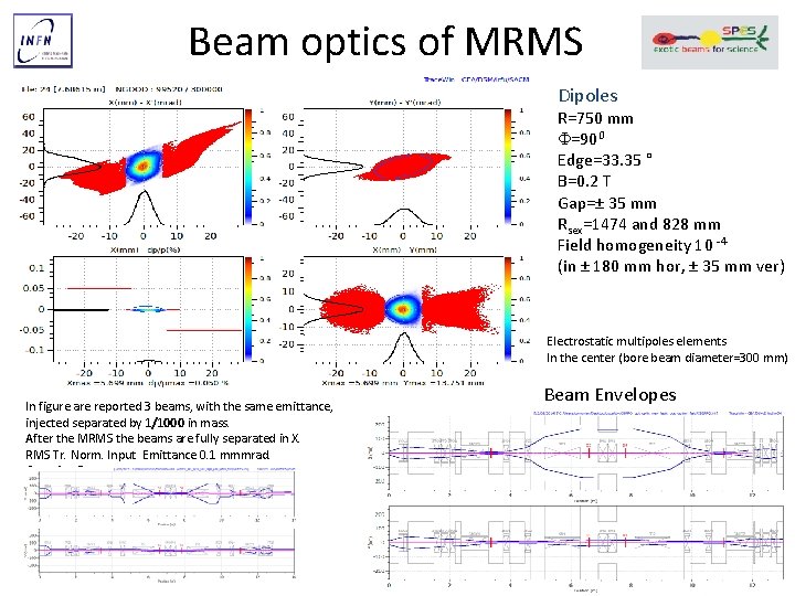
Beam optics of MRMS Dipoles R=750 mm F=900 Edge=33. 35 ° B=0. 2 T Gap=± 35 mm Rsex=1474 and 828 mm Field homogeneity 10 -4 (in ± 180 mm hor, ± 35 mm ver) Electrostatic multipoles elements In the center (bore beam diameter=300 mm) In figure are reported 3 beams, with the same emittance, injected separated by 1/1000 in mass. After the MRMS the beams are fully separated in X. RMS Tr. Norm. Input Emittance 0. 1 mmmrad. Gaussian Beam Envelopes
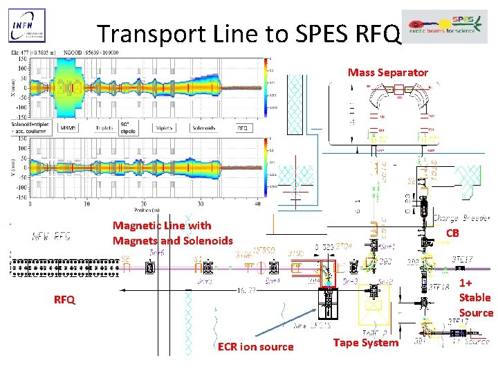
Transport Line to SPES RFQ Mass Separator Magnetic Line with Magnets and Solenoids CB 1+ Stable Source RFQ ECR ion source Tape System
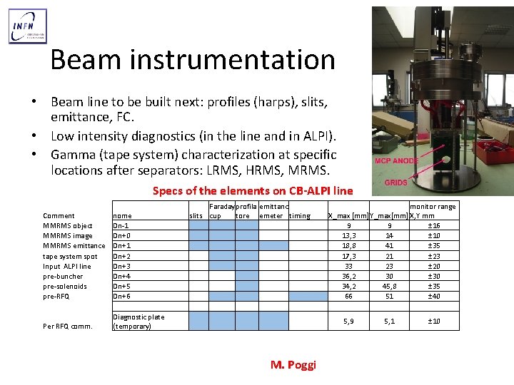
Beam instrumentation • Beam line to be built next: profiles (harps), slits, emittance, FC. • Low intensity diagnostics (in the line and in ALPI). • Gamma (tape system) characterization at specific locations after separators: LRMS, HRMS, MRMS. Specs of the elements on CB-ALPI line Comment MMRMS object MMRMS image MMRMS emittance tape system spot Input ALPI line pre-buncher pre-solenoids pre-RFQ Per RFQ comm. nome Dn-1 Dn+0 Dn+1 Dn+2 Dn+3 Dn+4 Dn+5 Dn+6 Diagnostic plate (temporary) slits Faraday profila cup tore emittanc emeter timing M. Poggi monitor range X_max [mm] Y_max[mm] X, Y mm 9 9 ± 16 13, 3 14 ± 10 18, 8 41 ± 35 17, 3 21 ± 23 33 23 ± 20 36, 2 30 ± 30 34, 2 45, 8 ± 35 66 51 ± 40 5, 9 5, 1 ± 10
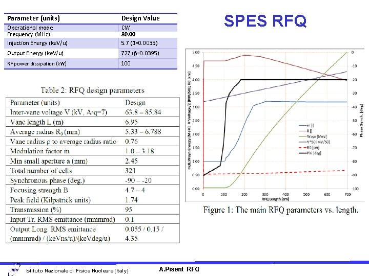
Parameter (units) Design Value Operational mode Frequency (MHz) Injection Energy (ke. V/u) CW 80. 00 5. 7 (β=0. 0035) Output Energy (ke. V/u) 727 (β=0. 0395) RF power dissipation (k. W) 100 Istituto Nazionale di Fisica Nucleare (Italy) SPES RFQ A. Pisent RFQ for cw applications Linac 10 -Tsukuba
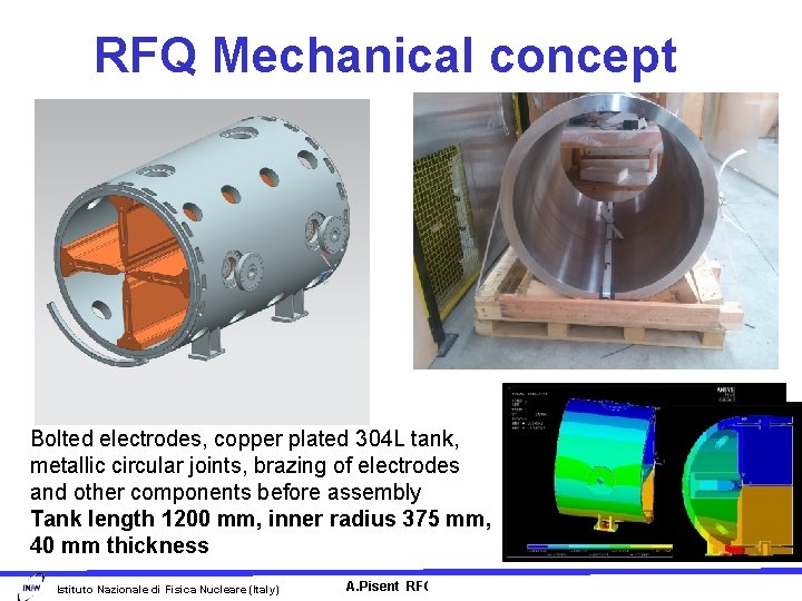
RFQ Mechanical concept Bolted electrodes, copper plated 304 L tank, metallic circular joints, brazing of electrodes and other components before assembly Tank length 1200 mm, inner radius 375 mm, 40 mm thickness Istituto Nazionale di Fisica Nucleare (Italy) A. Pisent RFQ for cw applications Linac 10 -Tsukuba
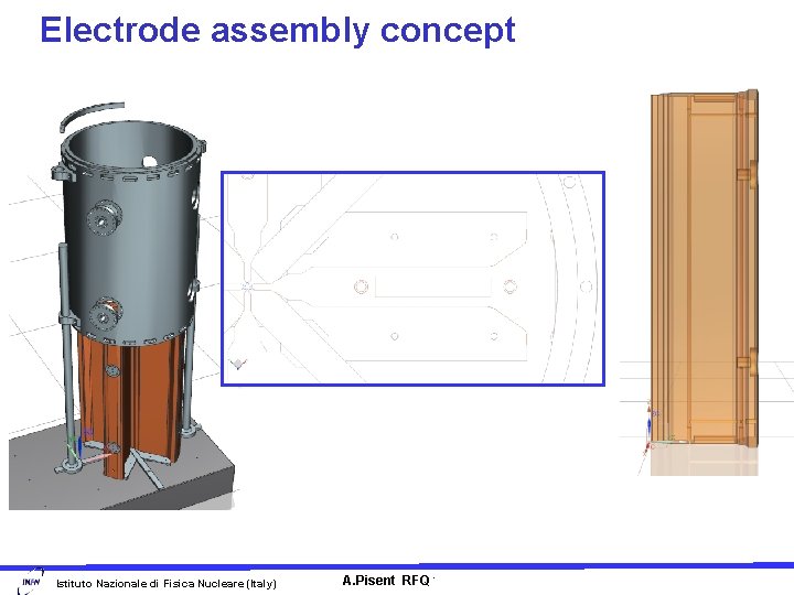
Electrode assembly concept Istituto Nazionale di Fisica Nucleare (Italy) A. Pisent RFQ for cw applications Linac 10 -Tsukuba
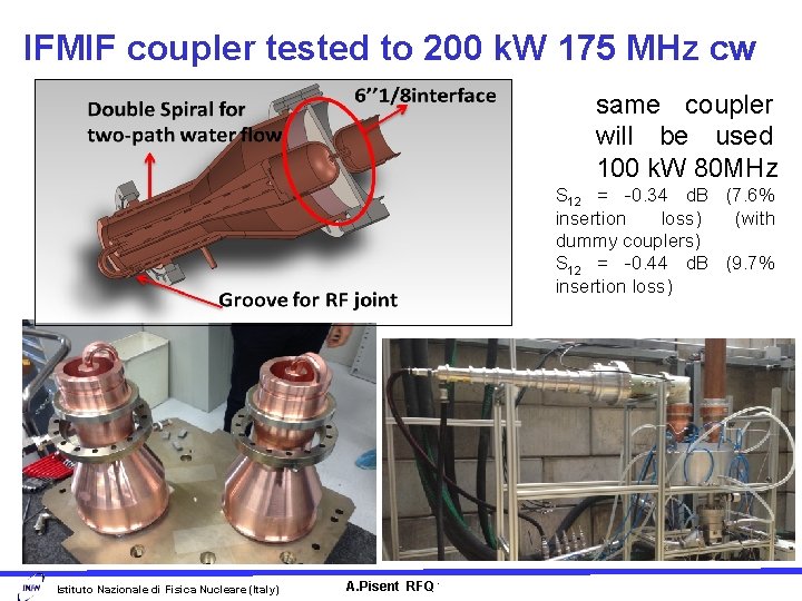
IFMIF coupler tested to 200 k. W 175 MHz cw same coupler will be used 100 k. W 80 MHz S 12 = -0. 34 d. B (7. 6% insertion loss) (with dummy couplers) S 12 = -0. 44 d. B (9. 7% insertion loss) Istituto Nazionale di Fisica Nucleare (Italy) A. Pisent RFQ for cw applications Linac 10 -Tsukuba
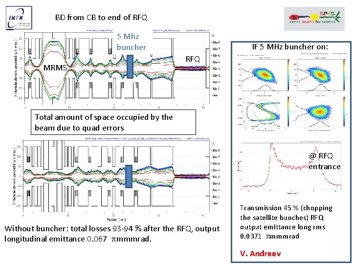
BD from CB to end of RFQ 5 Mhz buncher MRMS IF 5 MHz buncher on: RFQ Total amount of space occupied by the beam due to quad errors @ RFQ entrance Without buncher: total losses 93 -94 % after the RFQ, output longitudinal emittance 0. 067 mmmrad. Transmission 45 % (chopping the satellite bunches) RFQ output emittance long rms 0. 0371 mmmrad V. Andreev
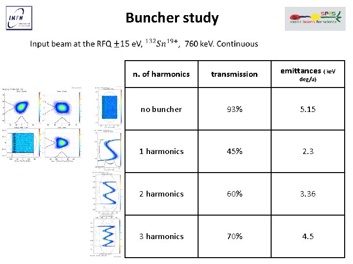
Buncher study n. of harmonics transmission emittances ( ke. V no buncher 93% 5. 15 1 harmonics 45% 2. 3 2 harmonics 60% 3. 36 3 harmonics 70% 4. 5 deg/u)
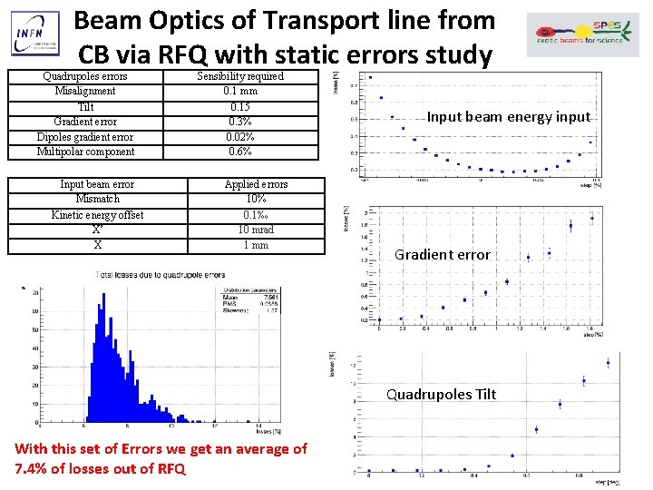
Beam Optics of Transport line from CB via RFQ with static errors study Quadrupoles errors Misalignment Sensibility required 0. 1 mm Tilt Gradient error Dipoles gradient error Multipolar component 0. 15 0. 3% 0. 02% 0. 6% Input beam error Mismatch Kinetic energy offset X’ X Applied errors 10% 0. 1‰ 10 mrad 1 mm Input beam energy input Gradient error Quadrupoles Tilt With this set of Errors we get an average of 7. 4% of losses out of RFQ
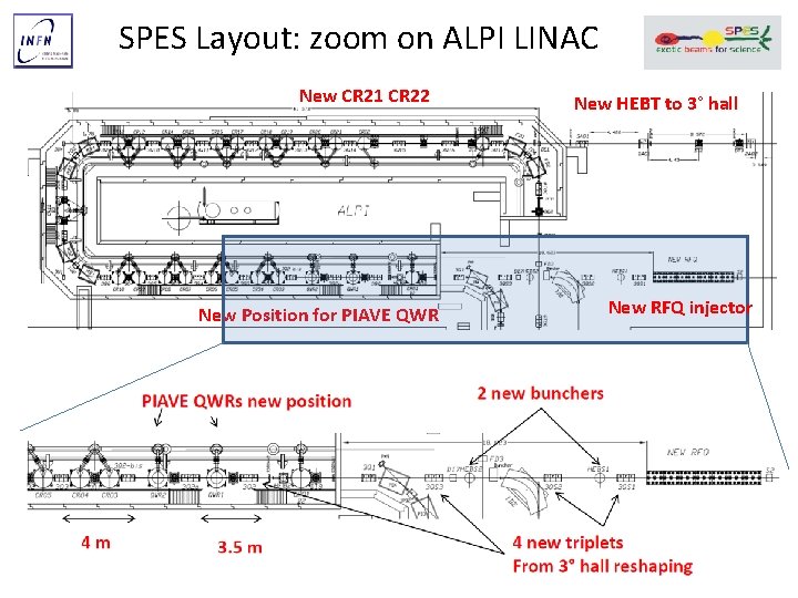
SPES Layout: zoom on ALPI LINAC New CR 21 CR 22 New Position for PIAVE QWR New HEBT to 3° hall New RFQ injector
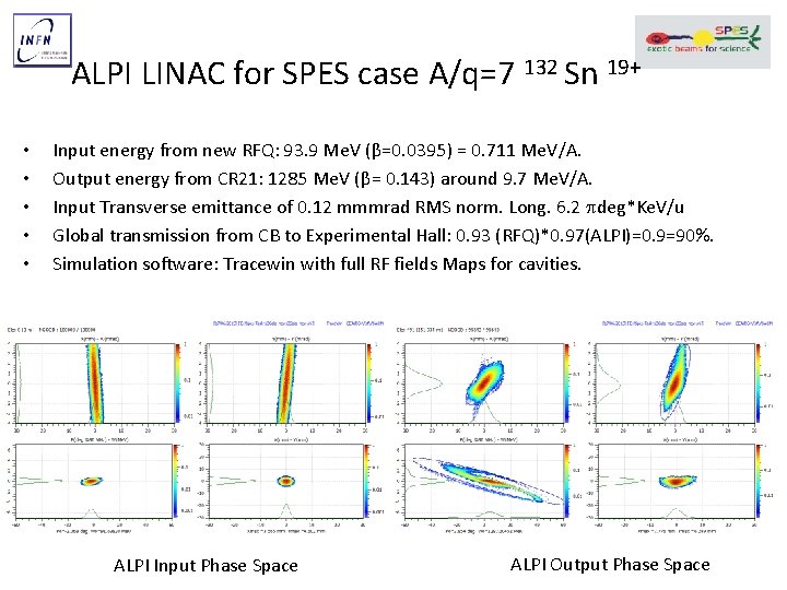
ALPI LINAC for SPES case A/q=7 132 Sn 19+ • • • Input energy from new RFQ: 93. 9 Me. V (β=0. 0395) = 0. 711 Me. V/A. Output energy from CR 21: 1285 Me. V (β= 0. 143) around 9. 7 Me. V/A. Input Transverse emittance of 0. 12 mmmrad RMS norm. Long. 6. 2 deg*Ke. V/u Global transmission from CB to Experimental Hall: 0. 93 (RFQ)*0. 97(ALPI)=0. 9=90%. Simulation software: Tracewin with full RF fields Maps for cavities. ALPI Input Phase Space ALPI Output Phase Space
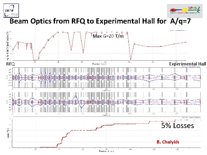
Beam Optics from RFQ to Experimental Hall for A/q=7 Max G=20 T/m RFQ Experimental Hall 5% Losses B. Chalykh
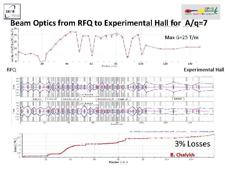
Beam Optics from RFQ to Experimental Hall for A/q=7 Max G=25 T/m RFQ Experimental Hall 3% Losses B. Chalykh
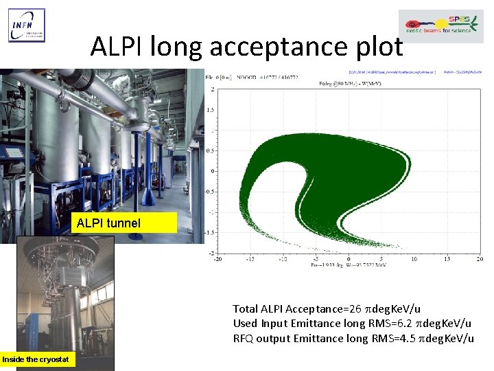
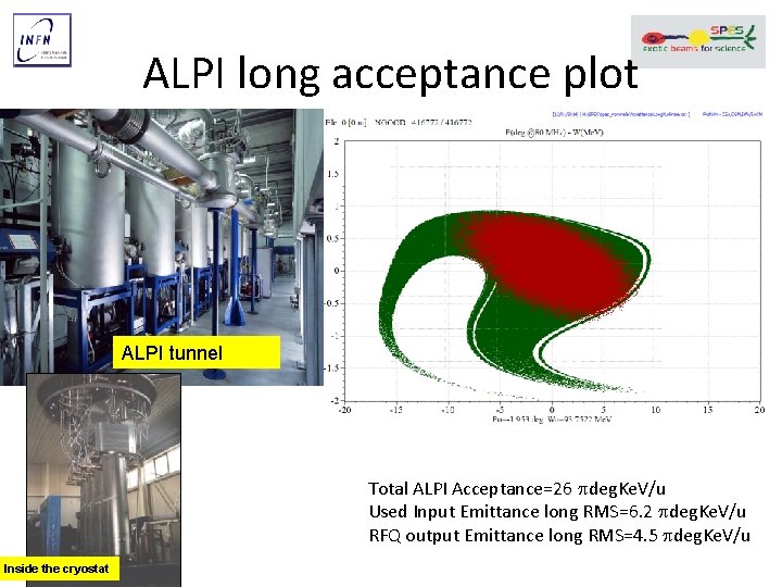
ALPI long acceptance plot ALPI tunnel Total ALPI Acceptance=26 deg. Ke. V/u Used Input Emittance long RMS=6. 2 deg. Ke. V/u RFQ output Emittance long RMS=4. 5 deg. Ke. V/u Inside the cryostat
ALPI long acceptance plot ALPI tunnel Total ALPI Acceptance=26 deg. Ke. V/u Used Input Emittance long RMS=6. 2 deg. Ke. V/u RFQ output Emittance long RMS=4. 5 deg. Ke. V/u Inside the cryostat
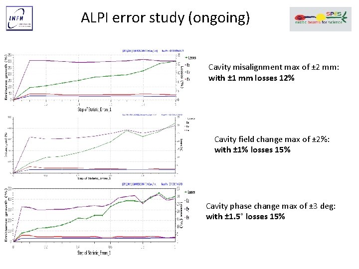
ALPI error study (ongoing) Cavity misalignment max of ± 2 mm: with ± 1 mm losses 12% Cavity field change max of ± 2%: with ± 1% losses 15% Cavity phase change max of ± 3 deg: with ± 1. 5° losses 15%
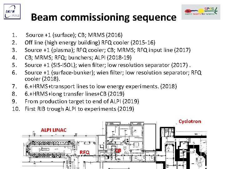
Beam commissioning sequence 1. 2. 3. 4. 5. 6. Source +1 (surface); CB; MRMS (2016) Off line (high energy building) RFQ cooler (2015 -16) Source +1 (plasma); RFQ cooler; CB; MRMS; RFQ input line (2017) CB; MRMS; RFQ; bunchers; ALPI (2018 -19) Source +1 (SIS-ISOL); wien filter; low resolution separator (2017). Source +1 (surface-bunker); wien filter; low resolution separator; RFQ cooler (2018). 7. 6. +HRMS+transport lines to low energy experiments. (2018) 8. 6. +HRMS+long transfer lines+CB (2019) 9. From production target to end of ALPI (2019) 10. First RIB trough ALPI to experiments (2019) Cyclotron ALPI LINAC RFQ CB
Conclusions • SPES post accelerator beam design has involved the study of many critical devices, and the overall optimization to distribute the criticality. • The beam transport lines from CB to ALPI are specified and we are tendering the magnets. • The mechanical design of RFQ and HRMS will be completed during 2015; starting of procurement procedure will follow within 2015.
Beam characteristics and constrains • Emittance from plasma source: 70 mmmrad geom RMS @40 k. V (132 Sn 1+), + 40 e. V (laser and surface are better) • After RFQ cooler and with platform 6 mm mrad geom 99% @ 220 k. V (132 Sn 1+), +2 e. V. Resolution required for the 1/20000. • Input acceptance of CB +5 e. V, output 0. 1 mm mrad norm, +- 30 e. V. • MRMS with geometrical acceptance of 340 mm mrad. • ALPI longitudinal acceptance (26 deg. Ke. V/u) and RFQ output longitudinal rms emittance (4. 3 deg. Ke. V/u).