Supporting VUNI in DRNI Maarten Vissers 2011 11



- Slides: 18
Supporting VUNI in DRNI Maarten Vissers 2011 -11 -10 v 01: added multiple virtual UNI with hairpin 1
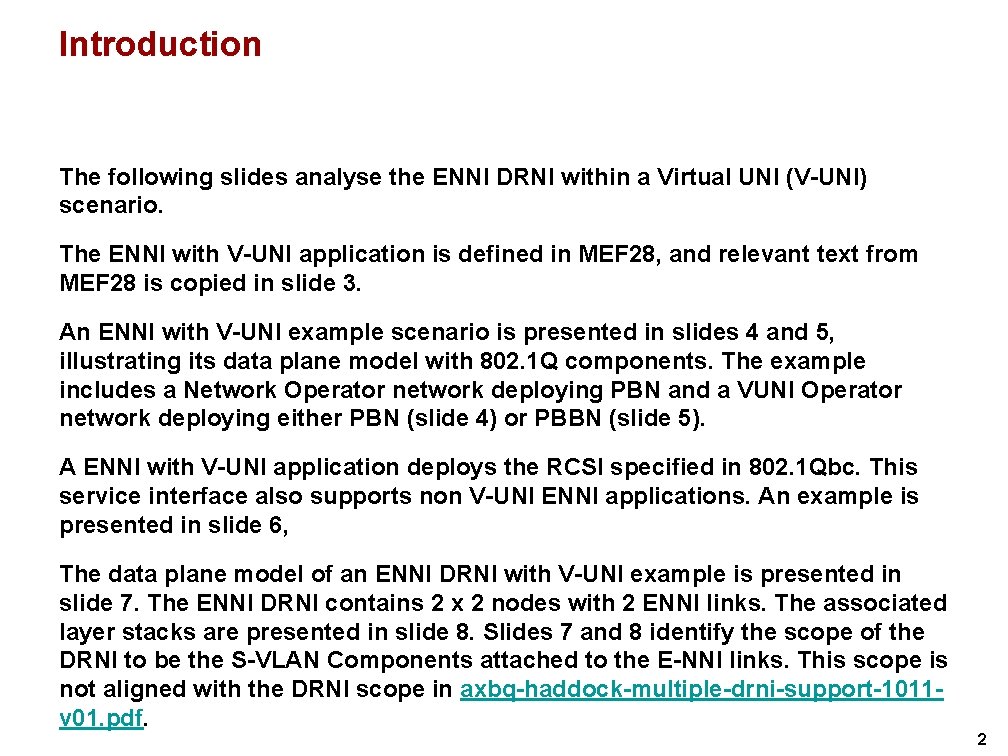
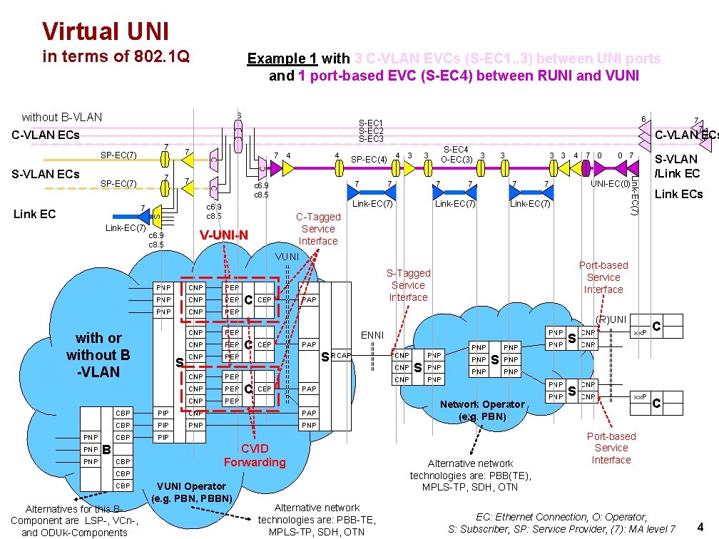
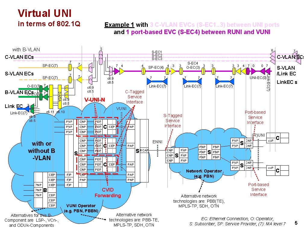
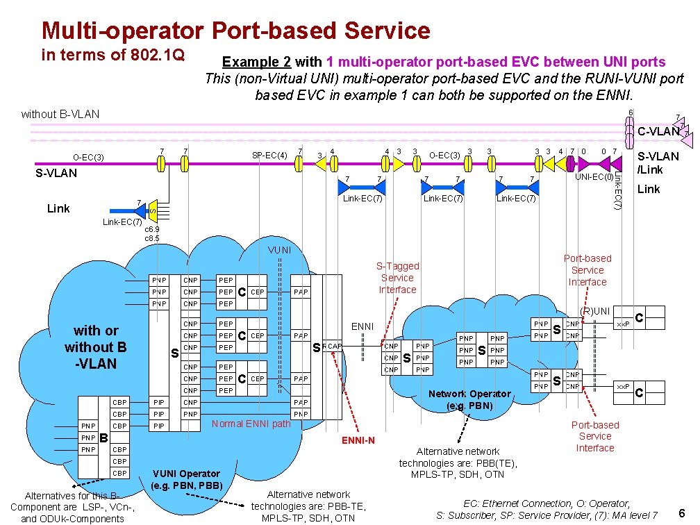
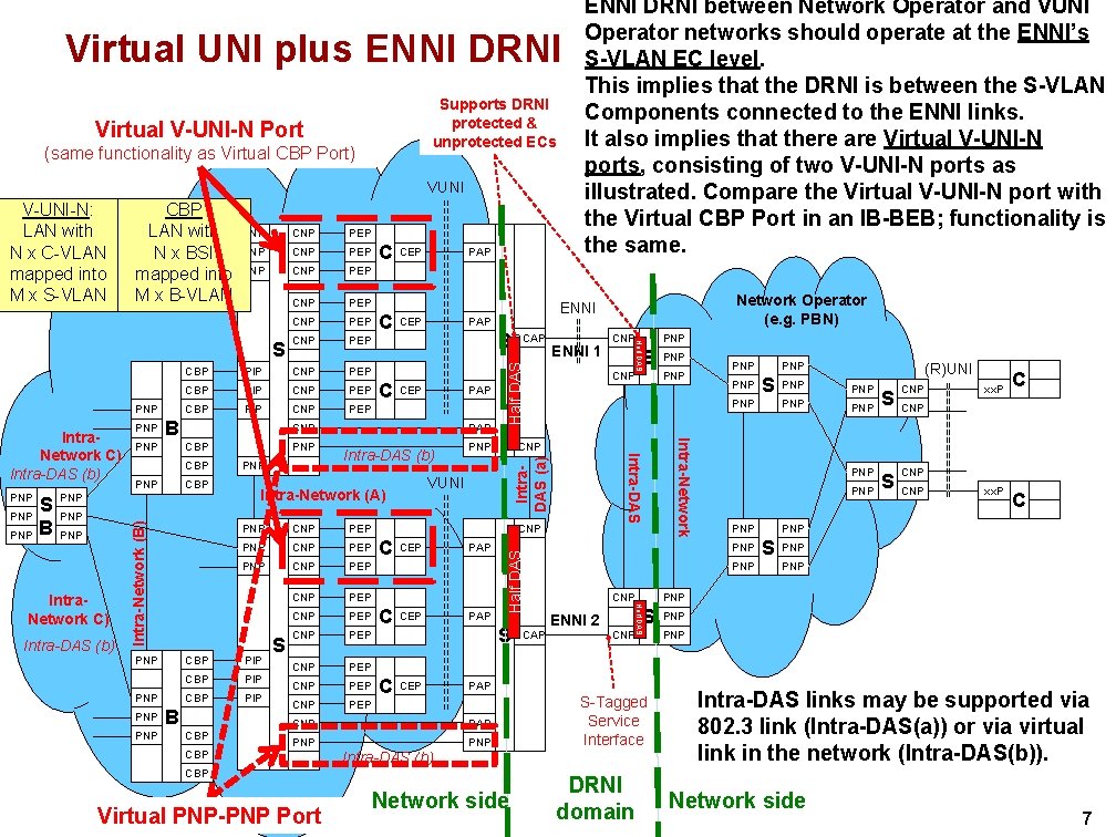
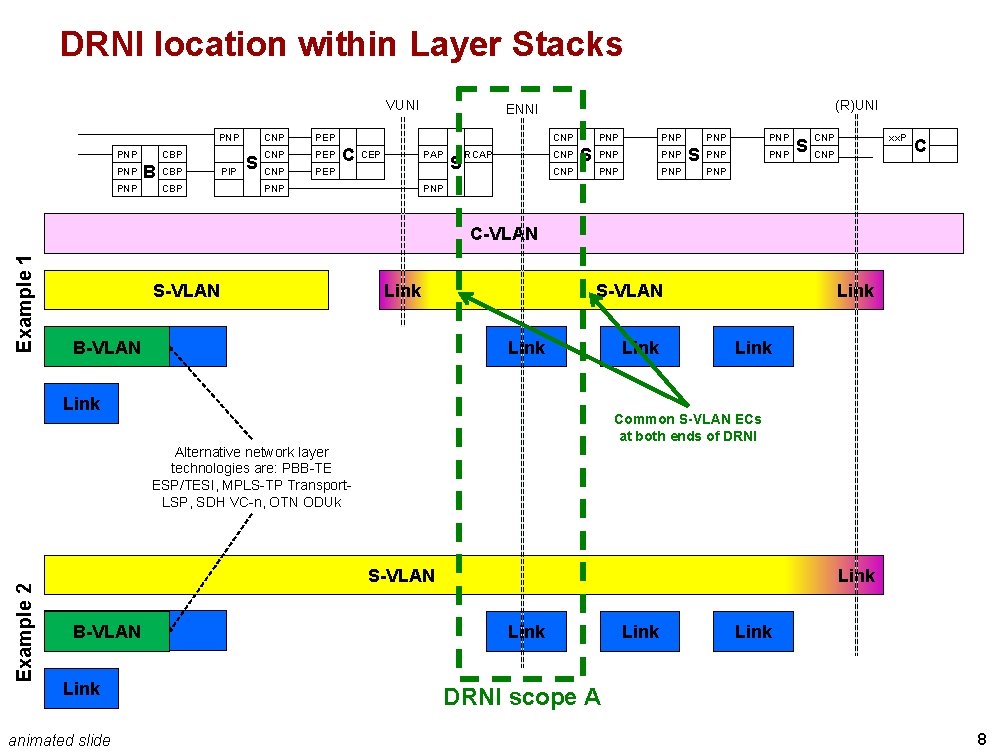
Introduction The following slides analyse the ENNI DRNI within a Virtual UNI (V-UNI) scenario. The ENNI with V-UNI application is defined in MEF 28, and relevant text from MEF 28 is copied in slide 3. An ENNI with V-UNI example scenario is presented in slides 4 and 5, illustrating its data plane model with 802. 1 Q components. The example includes a Network Operator network deploying PBN and a VUNI Operator network deploying either PBN (slide 4) or PBBN (slide 5). A ENNI with V-UNI application deploys the RCSI specified in 802. 1 Qbc. This service interface also supports non V-UNI ENNI applications. An example is presented in slide 6, The data plane model of an ENNI DRNI with V-UNI example is presented in slide 7. The ENNI DRNI contains 2 x 2 nodes with 2 ENNI links. The associated layer stacks are presented in slide 8. Slides 7 and 8 identify the scope of the DRNI to be the S-VLAN Components attached to the E-NNI links. This scope is not aligned with the DRNI scope in axbq-haddock-multiple-drni-support-1011 v 01. pdf. 2
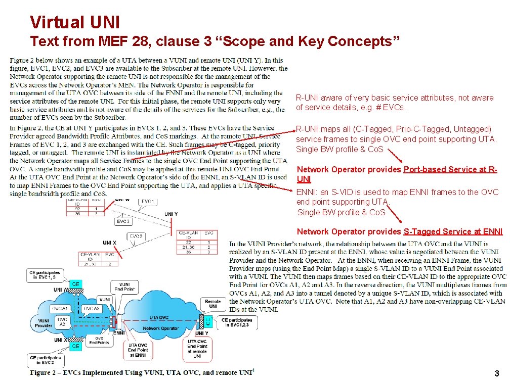
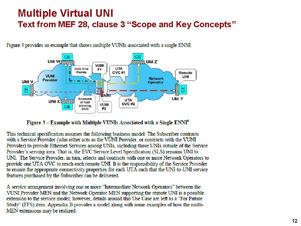
Virtual UNI Text from MEF 28, clause 3 “Scope and Key Concepts” R-UNI aware of very basic service attributes, not aware of service details, e. g. # EVCs. R-UNI maps all (C-Tagged, Prio-C-Tagged, Untagged) service frames to single OVC end point supporting UTA. Single BW profile & Co. S Network Operator provides Port-based Service at RUNI ENNI: an S-VID is used to map ENNI frames to the OVC end point supporting UTA. Single BW profile & Co. S Network Operator provides S-Tagged Service at ENNI 3
Virtual UNI in terms of 802. 1 Q Example 1 with 3 C-VLAN EVCs (S-EC 1. . 3) between UNI ports and 1 port-based EVC (S-EC 4) between RUNI and VUNI 6 without B-VLAN C-VLAN ECs 7 7 7 4 4 SP-EC(4) 4 3 S-EC 4 O-EC(3) 3 3 3 4 7 0 0 7 7 7 S Link-EC(7) 7 7 7 Link-EC(7) UNI-EC(0) 7 Link-EC(7) C-Tagged Service Interface V-UNI-N c 6. 9 c 8. 5 7 Link-EC(7) c 6. 9 c 8. 5 7 Link EC 7 c 6. 9 c 8. 5 C SP-EC(7) Link-EC(7) S-VLAN ECs VUNI PNP CNP PEP CNP PEP with or without B -VLAN PNP PNP S CNP PEP C CEP (R)UNI C C CEP S RCAP CEP CNP PAP CBP PIP PNP CBP PIP CVID Forwarding CBP Alternatives for this BComponent are LSP-, VCn-, and ODUk-Components VUNI Operator (e. g. PBN, PBBN) CNP PNP S PNP PNP S Alternative network technologies are: PBB-TE, MPLS-TP, SDH, OTN Link ECs PNP S CNP xx. P C CNP PNP PNP PAP PIP CBP PNP CBP B PNP ENNI PAP S-VLAN /Link EC Port-based Service Interface S-Tagged Service Interface PAP 7 7 C-VLAN ECs 7 C C SP-EC(7) 6 S-EC 1 S-EC 2 S-EC 3 Network Operator (e. g. PBN) Alternative network technologies are: PBB(TE), MPLS-TP, SDH, OTN PNP CNP xx. P C Port-based Service Interface EC: Ethernet Connection, O: Operator, S: Subscriber, SP: Service Provider, (7): MA level 7 4
Virtual UNI in terms of 802. 1 Q Example 1 with 3 C-VLAN EVCs (S-EC 1. . 3) between UNI ports and 1 port-based EVC (S-EC 4) between RUNI and VUNI with B-VLAN 6 C-VLAN ECs 7 4 SP-EC(4) 4 3 S-EC 4 O-EC(3) 3 3 3 4 7 0 0 7 C 7 B PNP CNP PEP CNP PEP with or without B -VLAN PNP PNP S CNP PEP C C CEP S RCAP CEP CNP PNP S PNP PNP S PIP PNP CBP PIP CVID Forwarding CBP Alternative network technologies are: PBB-TE, MPLS-TP, SDH, OTN Link. EC s PNP S CNP xx. P C CNP PNP PNP PAP CBP VUNI Operator (e. g. PBN, PBBN) PNP CNP S-VLAN /Link EC Port-based Service Interface PNP CNP PAP Alternatives for this BComponent are LSP-, VCn-, and ODUk-Components Link-EC(7) ENNI PAP CNP CBP Link-EC(7) UNI-EC(0) 7 (R)UNI PIP CBP 7 S-Tagged Service Interface PAP CBP B 7 VUNI c 6. 11 c 6. 10 c 6. 9 c 8. 5 7 C-Tagged Service Interface V-UNI-N c 6. 9 c 8. 5 7 Link-EC(7) S I 7 7 c 6. 9 c 8. 5 S 7 DA/SA B-VLAN ECs O-EC(7) 7 C SP-EC(7) O-EC(7) 7 Link-EC(7) 7 4 7 7 C-VLAN ECs 7 Link-EC(7) S-VLAN ECs Link EC 7 C SP-EC(7) 6 S-EC 1 S-EC 2 S-EC 3 Network Operator (e. g. PBN) Alternative network technologies are: PBB(TE), MPLS-TP, SDH, OTN PNP CNP xx. P C Port-based Service Interface EC: Ethernet Connection, O: Operator, S: Subscriber, SP: Service Provider, (7): MA level 7 5
Multi-operator Port-based Service in terms of 802. 1 Q Example 2 with 1 multi-operator port-based EVC between UNI ports This (non-Virtual UNI) multi-operator port-based EVC and the RUNI-VUNI port based EVC in example 1 can both be supported on the ENNI. without B-VLAN 6 7 7 C-VLAN 7 O-EC(3) 7 SP-EC(4) 7 3 4 4 7 7 O-EC(3) 3 7 Link-EC(7) 7 3 3 7 Link-EC(7) 4 7 0 0 7 UNI-EC(0) 7 Link-EC(7) S Link 3 Link-EC(7) S-VLAN 3 Link-EC(7) PNP CNP PEP CNP PEP with or without B -VLAN PNP S CNP PEP CBP PIP CNP CBP PIP PNP CBP PIP C CEP PAP (R)UNI C C CEP PNP ENNI PAP S RCAP PNP CNP CEP PNP S PNP Network Operator (e. g. PBN) ENNI-N Alternative network technologies are: PBB(TE), MPLS-TP, SDH, OTN CBP VUNI Operator (e. g. PBN, PBB) Alternative network technologies are: PBB-TE, MPLS-TP, SDH, OTN S S CNP xx. P C CNP PNP PAP PNP CNP PNP Normal ENNI path CBP Alternatives for this BComponent are LSP-, VCn-, and ODUk-Components Link Port-based Service Interface S-Tagged Service Interface PAP B CBP S-VLAN /Link c 6. 9 c 8. 5 VUNI PNP 7 PNP CNP xx. P C Port-based Service Interface EC: Ethernet Connection, O: Operator, S: Subscriber, SP: Service Provider, (7): MA level 7 6
Virtual UNI plus ENNI DRNI Supports DRNI protected & unprotected ECs Virtual V-UNI-N Port (same functionality as Virtual CBP Port) VUNI PEP PNP CNP PEP CNP PEP CBP PNP S B CNP PEP CBP PIP CNP PEP B PNP CBP PNP PNP Intra-DAS (b) PNP PNP S RCAP CEP PAP PNP PNP CNP PEP CNP PEP CNP PEP PIP CBP Intra-DAS (b) S PNP C C CEP PAP S RCAP CEP PAP PNP Virtual PNP-PNP Port Network side PNP PNP S CNP ENNI 2 S CNP S-Tagged Service Interface DRNI domain (R)UNI PNP PNP Intra-DAS (b) CBP PNP PAP CNP CBP S PNP CNP CNP CNP VUNI Intra-Network (A) CBP B PAP ENNI 1 Half DAS Intra. Network C) C PAP CNP Intra-Network (B) PNP PIP CEP Network Operator (e. g. PBN) ENNI Intra-Network PNP CBP PAP Intra-DAS Intra. Network C) Intra-DAS (b) PIP C CEP Intra. DAS (a) S C Half DAS CNP Half DAS PNP Half DAS V-UNI-N: CBP VUNI LAN with N x C-VLAN Operator N x BSI mapped into M x S-VLAN M x B-VLAN ENNI DRNI between Network Operator and VUNI Operator networks should operate at the ENNI’s S-VLAN EC level. This implies that the DRNI is between the S-VLAN Components connected to the ENNI links. It also implies that there are Virtual V-UNI-N ports, consisting of two V-UNI-N ports as illustrated. Compare the Virtual V-UNI-N port with the Virtual CBP Port in an IB-BEB; functionality is the same. S CNP xx. P C PNP S PNP PNP PNP Intra-DAS links may be supported via 802. 3 link (Intra-DAS(a)) or via virtual link in the network (Intra-DAS(b)). Network side 7
DRNI location within Layer Stacks VUNI PNP PNP CBP B PNP CBP PIP S CNP PEP (R)UNI ENNI CNP C CEP PAP PNP S RCAP CNP S PNP PNP PNP S CNP xx. P CNP C PNP Example 1 C-VLAN S-VLAN Link B-VLAN Link S-VLAN Link Link Common S-VLAN ECs at both ends of DRNI Example 2 Alternative network layer technologies are: PBB-TE ESP/TESI, MPLS-TP Transport. LSP, SDH VC-n, OTN ODUk S-VLAN Link B-VLAN Link animated slide Link DRNI scope A 8
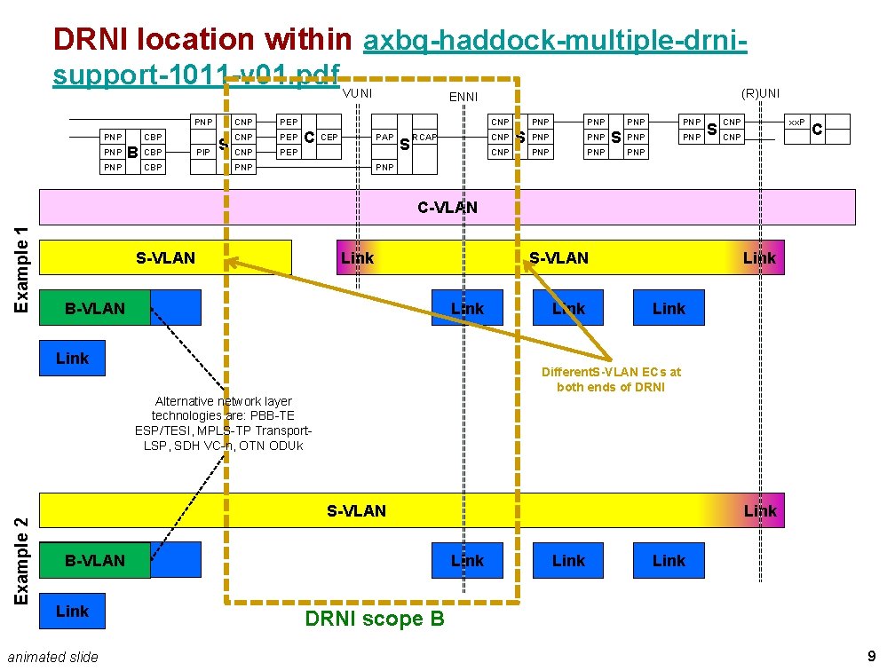
DRNI location within axbq-haddock-multiple-drnisupport-1011 -v 01. pdf VUNI PNP PNP CBP B PNP CBP PIP S CNP PEP (R)UNI ENNI CNP C CEP PAP PNP S RCAP CNP S PNP PNP PNP S CNP xx. P CNP C PNP Example 1 C-VLAN S-VLAN Link B-VLAN Link S-VLAN Link Link Different. S-VLAN ECs at both ends of DRNI Example 2 Alternative network layer technologies are: PBB-TE ESP/TESI, MPLS-TP Transport. LSP, SDH VC-n, OTN ODUk S-VLAN Link B-VLAN Link animated slide Link DRNI scope B 9
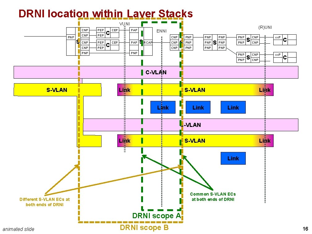
DRNI scope discussion axbq-haddock-multiple-drni-support-1011 -v 01. pdf (slide 9) and this presentation (slides 7/8) assume that the DRNI includes different sets of 802. 1 Q Components as illustrated in slides 7/8 (scope A) and 9 (scope B) To be discussed is the right DRNI scope: A, B or other 10
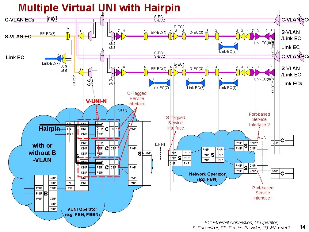
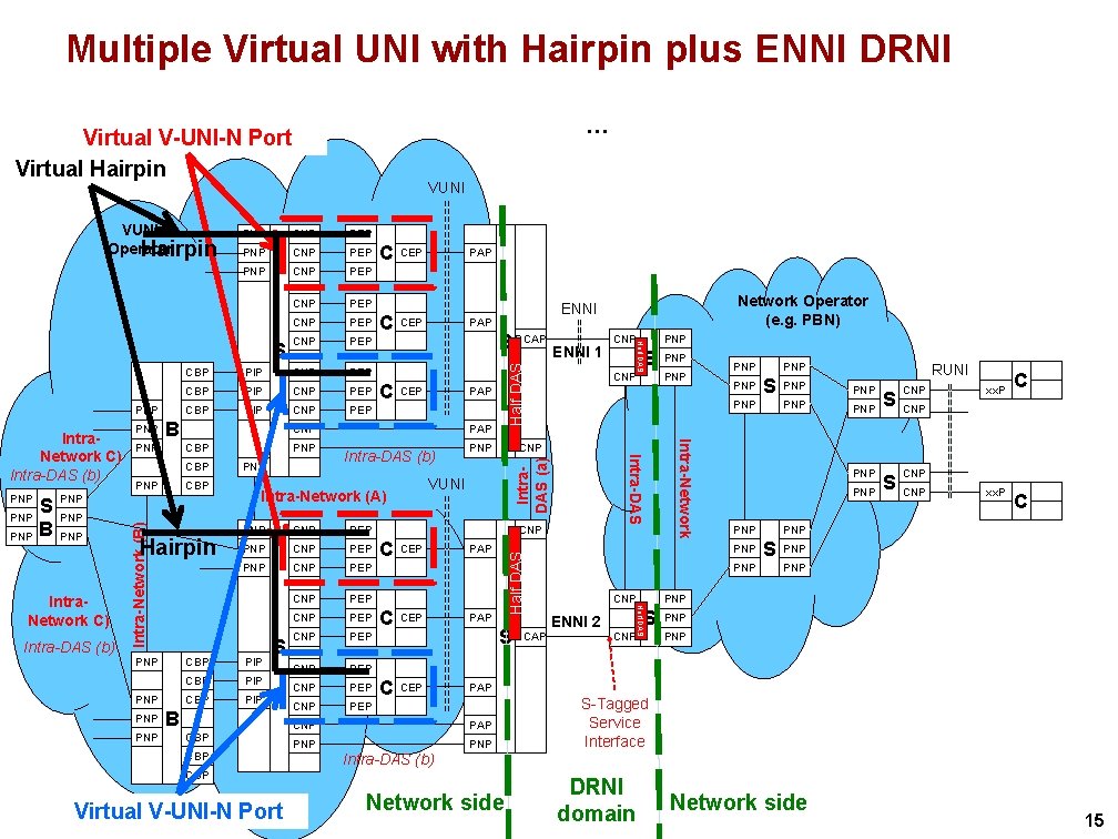
Multiple VUNIs, including hairpin 11
Multiple Virtual UNI Text from MEF 28, clause 3 “Scope and Key Concepts” 12
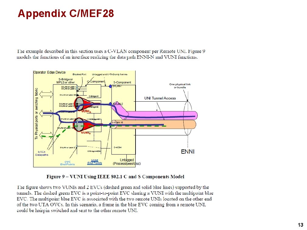
Appendix C/MEF 28 13
Multiple Virtual UNI with Hairpin 6 S-EC 3 7 C 4 SP-EC(4) 4 3 7 4 C Hairpin 4 7 0 c 6. 9 c 8. 5 4 S-EC 4 SP-EC(4) 4 3 3 7 7 O-EC(3) 3 7 Link-EC(7) 3 7 3 3 7 Link-EC(7) 4 7 0 CNP PEP PNP CNP PEP with or without B -VLAN PNP PNP S CNP PEP C CEP RUNI C C CEP S RCAP PNP CNP CEP PNP S PNP PNP S CNP PAP CBP PIP PNP CBP PIP 7 C-VLAN 7 ECs 7 S-VLAN /Link ECs PNP S CNP xx. P C CNP PNP PNP PAP PIP CBP PNP ENNI PAP Link EC Port-based Service Interface 2 S-Tagged Service Interface PAP CBP B 0 7 Link-EC(7) VUNI PNP 6 UNI-EC(0) 7 7 C-VLAN 7 ECs 7 S-VLAN /Link EC UNI-EC(0) 7 C-Tagged Service Interface V-UNI-N Hairpin 0 7 Link-EC(7) C 7 3 3 Link-EC(7) S-EC 1 S-EC 2 S c 6. 9 c 8. 5 3 7 7 Link-EC(7) O-EC(3) 3 c 6. 9 c 8. 5 6 Link EC 3 Link-EC(7) S-VLAN EC 7 4 7 SP-EC(7) C C-VLAN ECs 6 S-EC 1 S-EC 2 Network Operator (e. g. PBN) PNP CNP xx. P C Port-based Service Interface ! CBP VUNI Operator (e. g. PBN, PBBN) EC: Ethernet Connection, O: Operator, S: Subscriber, SP: Service Provider, (7): MA level 7 14
Multiple Virtual UNI with Hairpin plus ENNI DRNI … Virtual V-UNI-N Port Virtual Hairpin PEP PNP CNP PEP CNP PEP CBP PNP S B CNP PEP CBP PIP CNP PEP B PNP CBP PNP PNP Intra-DAS (b) Hairpin PNP PNP S RCAP CEP PNP PAP Intra-DAS (b) PNP CNP PEP CNP PEP CNP PEP CBP PIP S B CBP PNP C C CEP PAP S RCAP CEP PNP PNP PNP S S CNP PNP PNP PNP ENNI 2 PNP PNP CNP RUNI PNP S CNP xx. P C PNP S PNP PNP PNP PAP CNP PAP PNP S-Tagged Service Interface Intra-DAS (b) CBP Virtual V-UNI-N Port S PNP CNP CNP CNP VUNI Intra-Network (A) ENNI 1 Half DAS Intra. Network C) C PAP CNP Intra-Network (B) PNP PIP CEP Network Operator (e. g. PBN) ENNI Intra-Network PNP CBP PAP Intra-DAS Intra. Network C) Intra-DAS (b) PIP C CEP Intra. DAS (a) S C Half DAS CNP Half DAS PNP Half DAS VUNI Operator Hairpin VUNI Network side DRNI domain Network side 15
DRNI location within Layer Stacks VUNI PNP S CNP PEP C C CEP PAP (R)UNI ENNI PAP CNP S RCAP CNP S CNP PNP PNP S PNP PNP S CNP xx. P C CNP PNP PNP C-VLAN S-VLAN Link Link C-VLAN Link S-VLAN Link Common S-VLAN ECs at both ends of DRNI Different S-VLAN ECs at both ends of DRNI scope A animated slide DRNI scope B 16
Backup 17
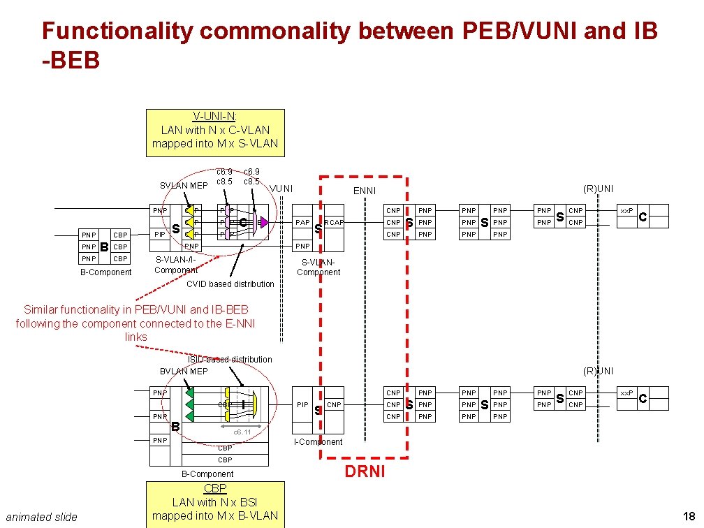
Functionality commonality between PEB/VUNI and IB -BEB V-UNI-N: LAN with N x C-VLAN mapped into M x S-VLAN c 6. 9 SVLAN MEP c 8. 5 PNP PNP CBP B PIP S CNP PEP CBP PNP CBP S-VLAN-/IComponent B-Component c 6. 9 c 8. 5 VUNI (R)UNI ENNI CNP C CEP PAP S RCAP CNP S CNP PNP PNP PNP S CNP xx. P C CNP PNP S-VLANComponent CVID based distribution Similar functionality in PEB/VUNI and IB-BEB following the component connected to the E-NNI links ISID based distribution BVLAN MEP (R)UNI PNP CBP PNP B I S CNP CNP S PNP PNP PNP S CNP PNP c 6. 11 PNP CBP B-Component animated slide PIP PNP CBP LAN with N x BSI mapped into M x B-VLAN I-Component DRNI 18