Soft XRay Tomography in HSX V Sakaguchi A


- Slides: 27
Soft X-Ray Tomography in HSX V. Sakaguchi, A. F. Almagri, D. T. Anderson, F. S. B. Anderson, K. Likin & the HSX Team The HSX Plasma Laboratory University of Wisconsin-Madison
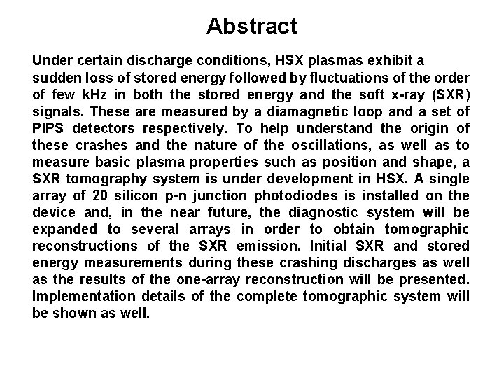
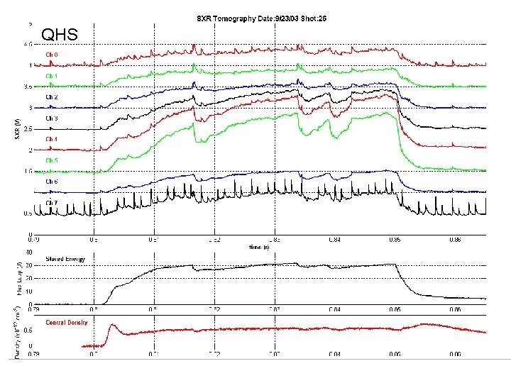
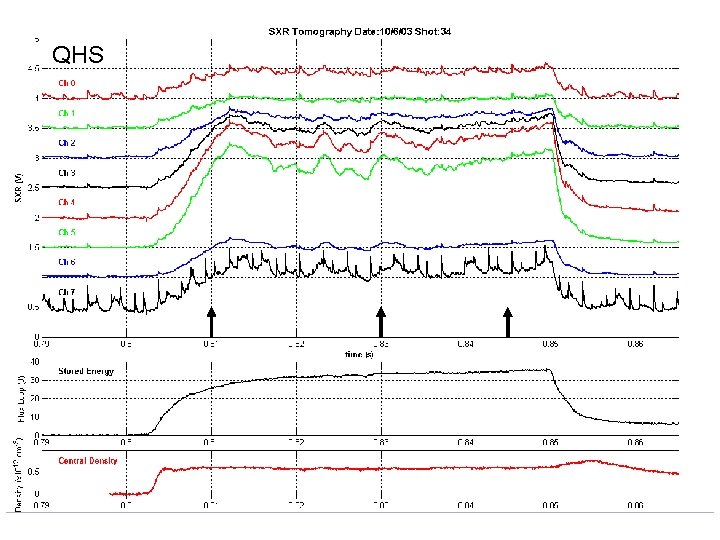
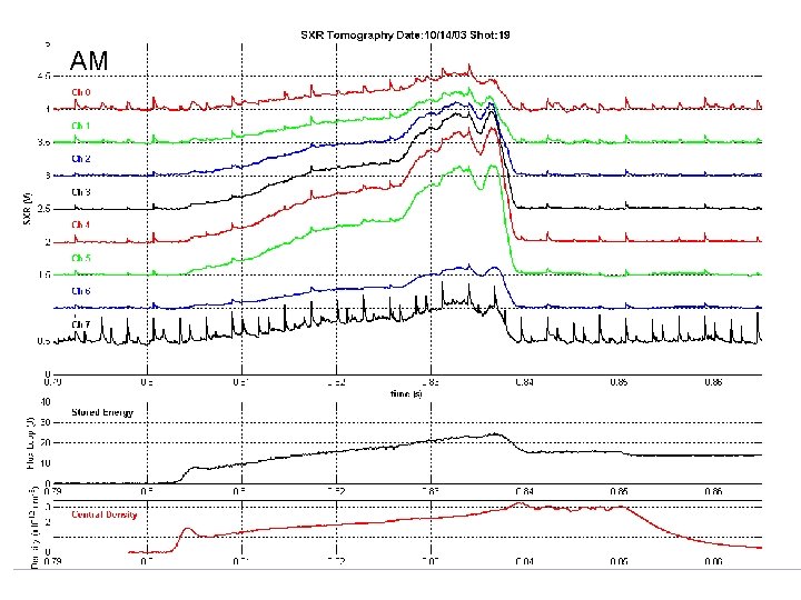
Abstract Under certain discharge conditions, HSX plasmas exhibit a sudden loss of stored energy followed by fluctuations of the order of few k. Hz in both the stored energy and the soft x-ray (SXR) signals. These are measured by a diamagnetic loop and a set of PIPS detectors respectively. To help understand the origin of these crashes and the nature of the oscillations, as well as to measure basic plasma properties such as position and shape, a SXR tomography system is under development in HSX. A single array of 20 silicon p-n junction photodiodes is installed on the device and, in the near future, the diagnostic system will be expanded to several arrays in order to obtain tomographic reconstructions of the SXR emission. Initial SXR and stored energy measurements during these crashing discharges as well as the results of the one-array reconstruction will be presented. Implementation details of the complete tomographic system will be shown as well.
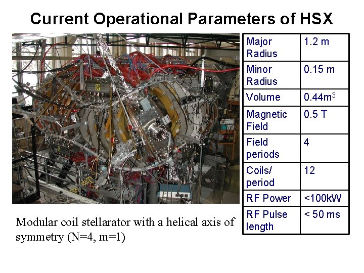
Current Operational Parameters of HSX Modular coil stellarator with a helical axis of symmetry (N=4, m=1) Major Radius 1. 2 m Minor Radius 0. 15 m Volume 0. 44 m 3 Magnetic Field 0. 5 T Field periods 4 Coils/ period 12 RF Power <100 k. W RF Pulse length < 50 ms
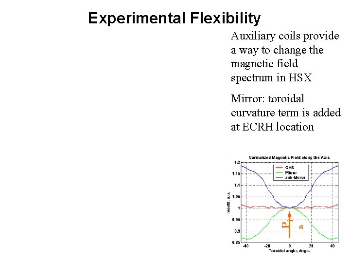
Experimental Flexibility Auxiliary coils provide a way to change the magnetic field spectrum in HSX n Pi Mirror: toroidal curvature term is added at ECRH location
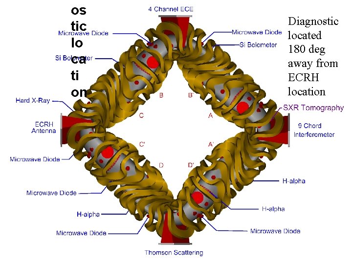
os tic lo ca ti on Diagnostic located 180 deg away from ECRH location
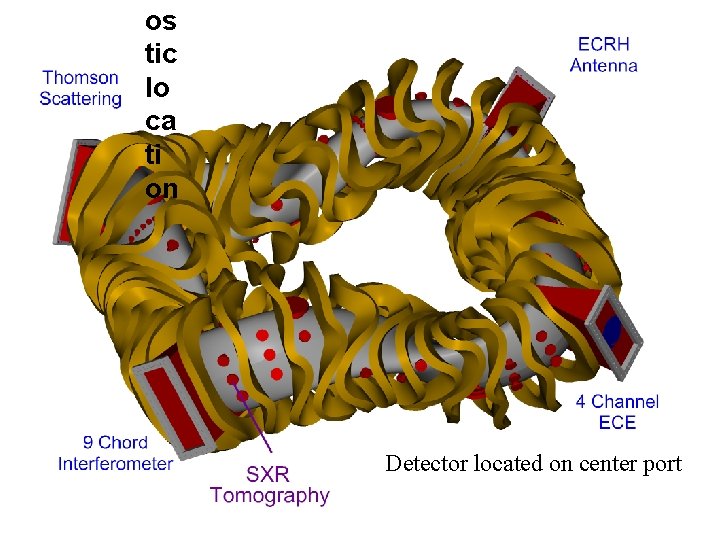
os tic lo ca ti on Detector located on center port
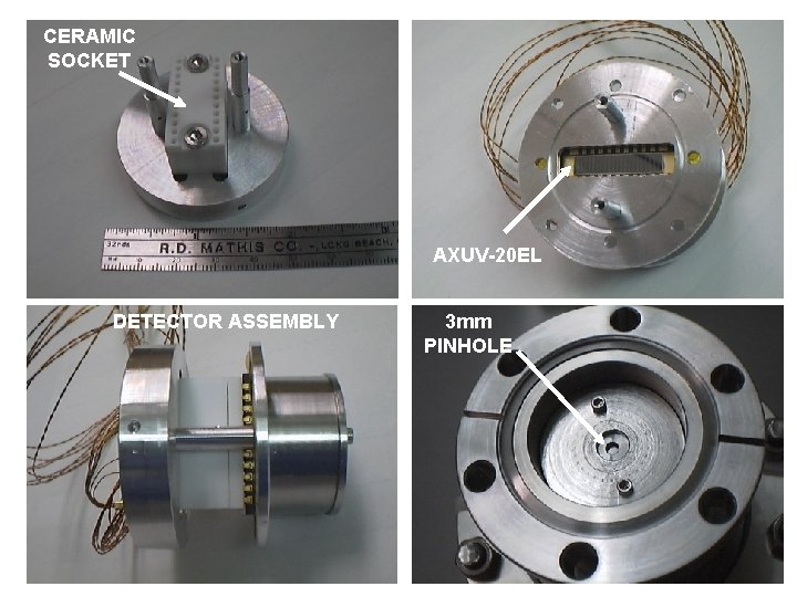
CERAMIC SOCKET AXUV-20 EL DETECTOR ASSEMBLY 3 mm PINHOLE
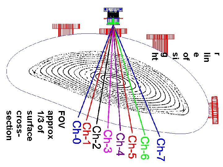
r lin e of si g ht FOV approx 1/3 of surface crosssection
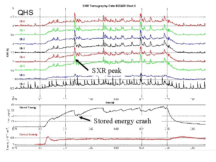
QHS SXR peak Stored energy crash
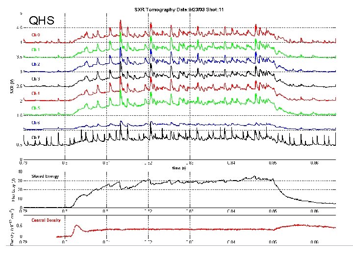
QHS
QHS
QHS
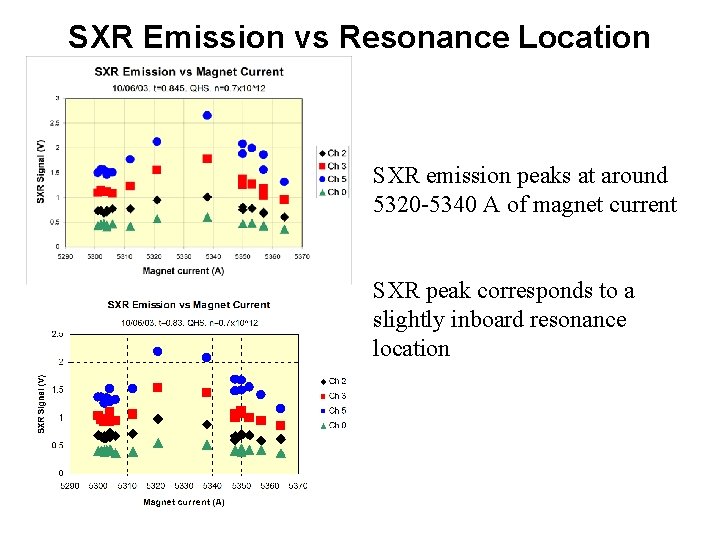
SXR Emission vs Resonance Location SXR emission peaks at around 5320 -5340 A of magnet current SXR peak corresponds to a slightly inboard resonance location
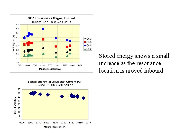
Stored energy shows a small increase as the resonance location is moved inboard
AM
AM
AM
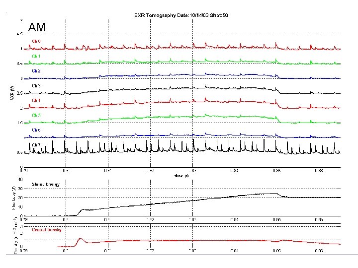
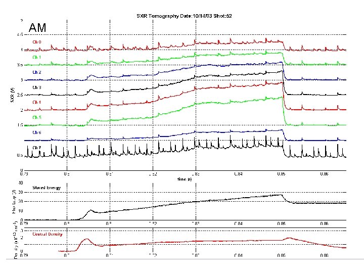
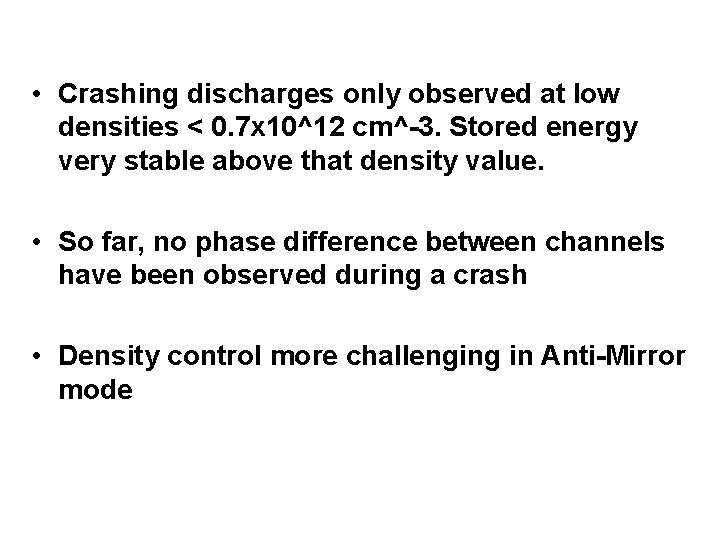
• Crashing discharges only observed at low densities < 0. 7 x 10^12 cm^-3. Stored energy very stable above that density value. • So far, no phase difference between channels have been observed during a crash • Density control more challenging in Anti-Mirror mode
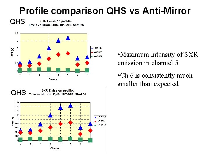
Profile comparison QHS vs Anti-Mirror QHS • Maximum intensity of SXR emission in channel 5 • Ch 6 is consistently much smaller than expected QHS
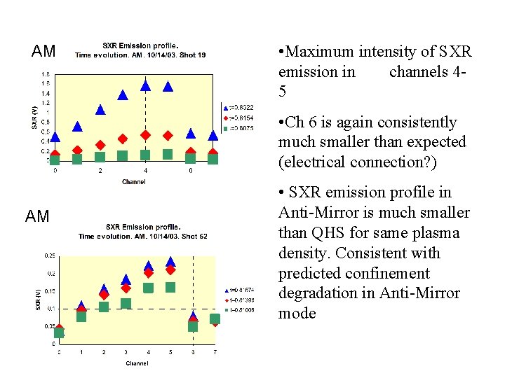
AM • Maximum intensity of SXR emission in channels 45 • Ch 6 is again consistently much smaller than expected (electrical connection? ) AM • SXR emission profile in Anti-Mirror is much smaller than QHS for same plasma density. Consistent with predicted confinement degradation in Anti-Mirror mode
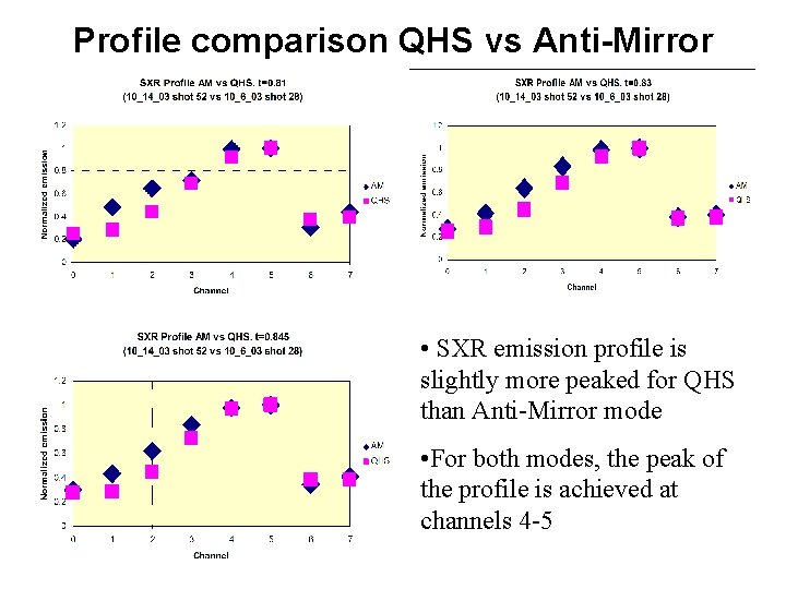
Profile comparison QHS vs Anti-Mirror • SXR emission profile is slightly more peaked for QHS than Anti-Mirror mode • For both modes, the peak of the profile is achieved at channels 4 -5
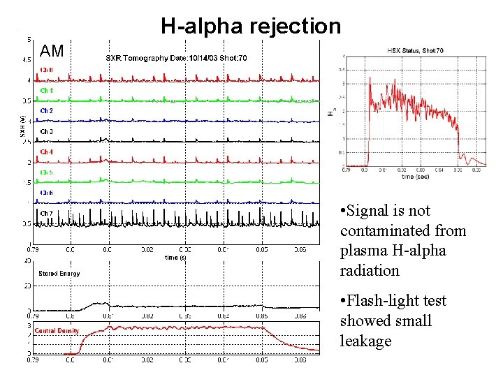
H-alpha rejection AM • Signal is not contaminated from plasma H-alpha radiation • Flash-light test showed small leakage
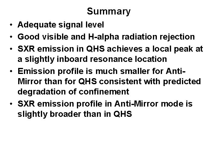
Summary • Adequate signal level • Good visible and H-alpha radiation rejection • SXR emission in QHS achieves a local peak at a slightly inboard resonance location • Emission profile is much smaller for Anti. Mirror than for QHS consistent with predicted degradation of confinement • SXR emission profile in Anti-Mirror mode is slightly broader than in QHS
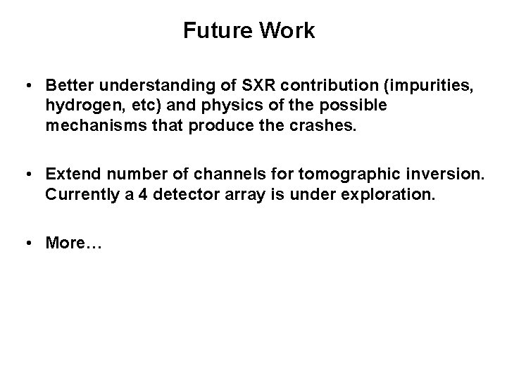
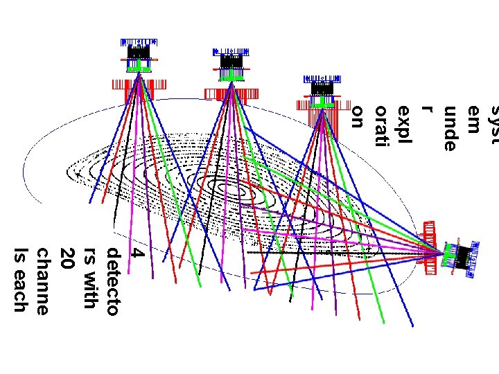
Future Work • Better understanding of SXR contribution (impurities, hydrogen, etc) and physics of the possible mechanisms that produce the crashes. • Extend number of channels for tomographic inversion. Currently a 4 detector array is under exploration. • More…
syst em unde r expl orati on 4 detecto rs with 20 channe ls each
Reprint Signup Please leave you name and either your e-mail address for an e-copy or physical address for a paper copy of this poster. Thank you for stopping by. Name Address