
The ConstellationX Spectroscopy Xray Telescope Recent Technology Development



- Slides: 23
The Constellation-X Spectroscopy X-ray Telescope: Recent Technology Development R. Petre, W. Zhang, T. Saha, D. Content, S. Owens, J. Stewart, J. Lehan /GSFC S. O’Dell, W. Jones / MSFC P. Reid / SAO
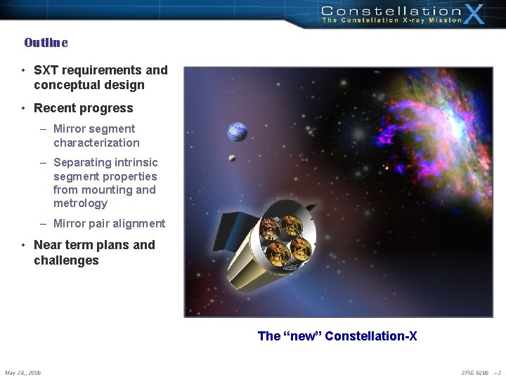
Outline • SXT requirements and conceptual design • Recent progress – Mirror segment characterization – Separating intrinsic segment properties from mounting and metrology – Mirror pair alignment • Near term plans and challenges The “new” Constellation-X May 29, , 2006 SPIE 6266 – 2
SXT Flight Mirror Assembly Requirements (per mirror) • • May 29, , 2006 The fundamental SXT performance requirements have not changed over the past several years Emphasis on performance margin (extra effective area) and need to approach angular resolution goal has increased SPIE 6266 – 3
SXT Mirror Reference Design Concept SXT Incorporates Modular Construction and Segmented Wolter I Mirrors Primary (Paraboloid) (12 Outer Submodules) Primary (Paraboloid) (6 Inner submodules) 2 x 20 cm mirror length Ring Structure Assembly Secondary (Hyperboloid) (6 Inner, 12 Outer submodules) 1. 6 m diameter at P-H intersection May 29, , 2006 SPIE 6266 – 4
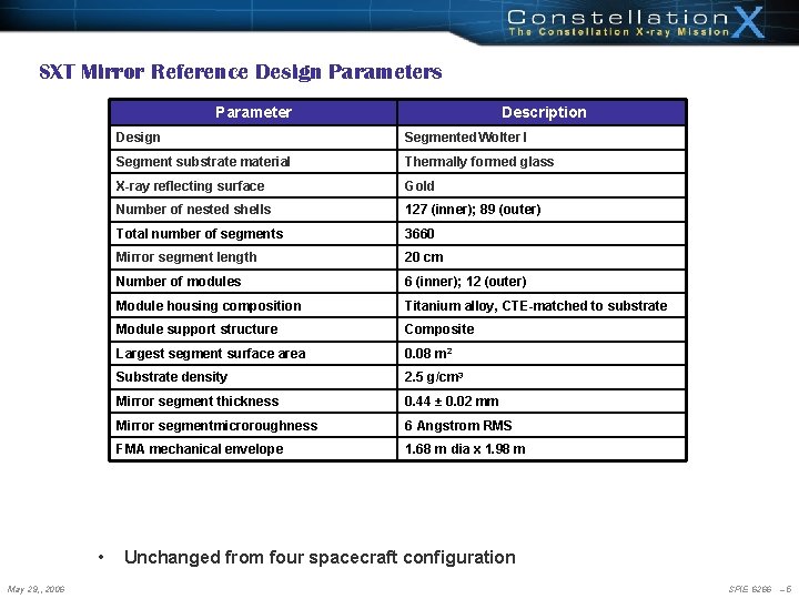
SXT Mirror Reference Design Parameters Parameter • May 29, , 2006 Description Design Segmented Wolter I Segment substrate material Thermally formed glass X-ray reflecting surface Gold Number of nested shells 127 (inner); 89 (outer) Total number of segments 3660 Mirror segment length 20 cm Number of modules 6 (inner); 12 (outer) Module housing composition Titanium alloy, CTE-matched to substrate Module support structure Composite Largest segment surface area 0. 08 m 2 Substrate density 2. 5 g/cm 3 Mirror segment thickness 0. 44 ± 0. 02 mm Mirror segmentmicroroughness 6 Angstrom RMS FMA mechanical envelope 1. 68 m dia x 1. 98 m Unchanged from four spacecraft configuration SPIE 6266 – 5
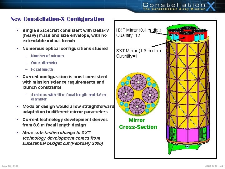
New Constellation-X Configuration • Single spacecraft consistent with Delta-IV (heavy) mass and size envelope, with no extendable optical bench • Numerous optical configurations studied – Number of mirrors HXT Mirror (0. 4 m dia. ) Quantity=12 SXT Mirror (1. 6 m dia. ) Quantity=4 – Outer diameter – Focal length • Current configuration is most consistent with mission science requirements and launch constraints – 4 mirrors with 10 m focal length and 1. 6 m diameter • Modular design would allow straightforward adaptation to different mirror parameters • Current technology development derives from 8. 6 m focal length design Mirror Cross-Section • More substantive change to SXT technology development comes from substantial budget cut (February 2006) May 29, , 2006 SPIE 6266 – 6
SXT Reference Concept Angular Resolution Error Budget May 29, , 2006 SPIE 6266 – 7
Mirror Segments - Recent Progress • Demonstrated that formed substrates faithfully and consistently reproduce the forming mandrel surface at low spatial frequencies • Improved the formed and replicated mirror quality by reduction of size and number of particulates (dust) on surface – Invested considerable effort reducing environmental dust in mirror lab • Demonstrated that replication with ~10 µm epoxy layer can smooth out mid-frequency errors without causing significant distortion to low order figure • Demonstrated feasibility of producing mirror segments meeting the error budget requirement without replication – Low and mid frequency improvement is likely if more precise forming mandrels are used • Demonstrated that low order figure distortions are very sensitive to segment orientation and how it is held • Developed a forming mandrel release layer that is very smooth and durable, and reduces mid-frequency roughness introduced by forming – Possible to apply using robotic spraying (developed for epoxy) – Process improvements still being sought May 29, , 2006 SPIE 6266 – 8
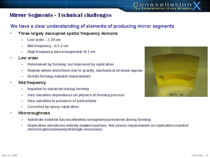
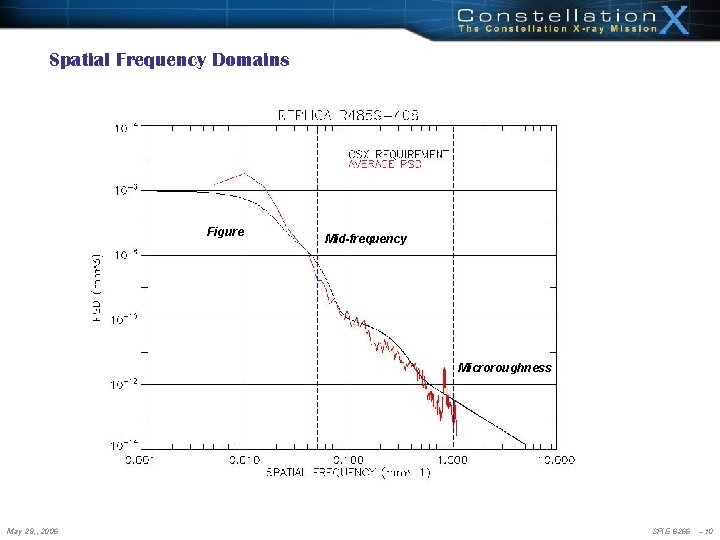
Mirror Segments - Technical challenges We have a clear understanding of elements of producing mirror segments • • May 29, , 2006 Three largely decoupled spatial frequency domains – Low order - 2 -20 cm – Mid-frequency - 0. 1 -2 cm – High-frequency (microroughness) <0. 1 cm Low order – Determined by forming; not improved by replication – Regime where distortions due to gravity, mechanical stresses appear – Dictate forming mandrel requirements Mid frequency – Imparted to substrate during forming – Very sensitive dependence on physics of forming process – Very sensitive to presence of particulates – Corrected by epoxy replication Microroughness – Substrate material has excellentmicroroughness; preserved during forming – Replication introduces entirely newmicrosurface- this places requirements on replication mandrel microroughness(superpolishingis necessary) SPIE 6266 – 9
Spatial Frequency Domains Figure Mid-frequency Microroughness May 29, , 2006 SPIE 6266 – 10
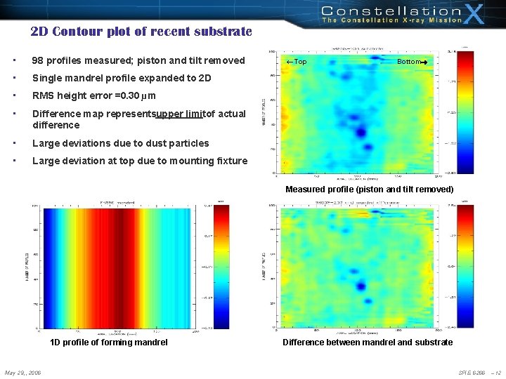
2 D Contour plot of recent substrate • 98 profiles measured; piston and tilt removed • Single mandrel profile expanded to 2 D • RMS height error =0. 30 µm • Difference map representsupper limitof actual difference • Large deviations due to dust particles • Large deviation at top due to mounting fixture ¬Top Bottom Measured profile (piston and tilt removed) 1 D profile of forming mandrel May 29, , 2006 Difference between mandrel and substrate SPIE 6266 – 12
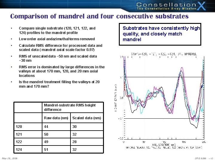
Comparison of mandrel and four consecutive substrates • Compare single substrate (120, 121, 122, and 124) profiles to the mandrel profile • Low order axial andazimuthal terms removed • Calculate RMS difference for processed data and scaled data ( mandrel axial scale factor 0. 97) • RMS of unscaled data ~50 nm and scaled data ~30 nm • RMS error is dominated by large differences in the valleys at about 170 mm, 120, and 20 mm axial locations • Is the mandrel treatment filling the valleys at 20 mm and 170 mm? Substrates have consistently high quality, and closely match mandrel Mandrel-substrate RMS height difference Raw data (nm) Scaled data (nm) 120 44 30 121 50 32 122 49 28 124 51 32 May 29, , 2006 SPIE 6266 – 13
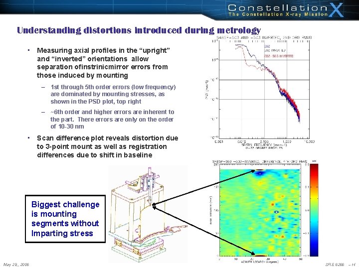
Understanding distortions introduced during metrology • Measuring axial profiles in the “upright” and “inverted” orientations allow separation ofinstrinicmirror errors from those induced by mounting – 1 st through 5 th order errors (low frequency) are dominated by mounting stresses, as shown in the PSD plot, top right – ~6 th order and higher errors are inherent to the part. There errors are only on the order of 10 -30 nm • Scan difference plot reveals distortion due to 3 -point mount as well as registration differences due to shift in baseline Biggest challenge is mounting segments without Imparting stress May 29, , 2006 SPIE 6266 – 14
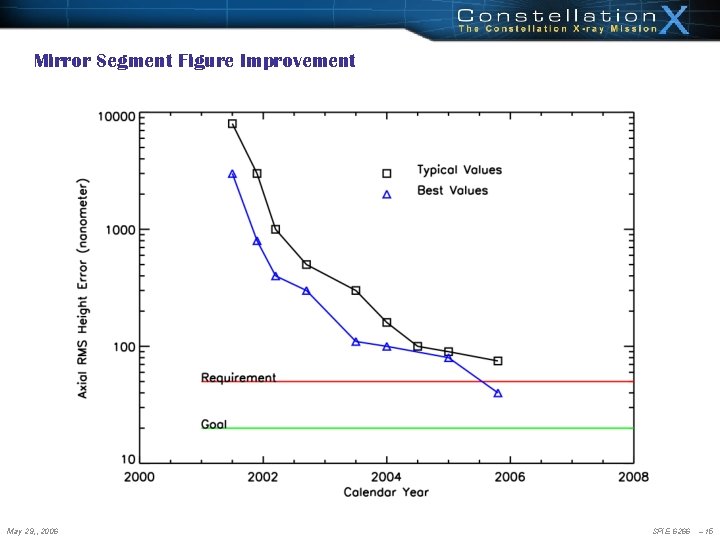
Mirror Segment Figure Improvement May 29, , 2006 SPIE 6266 – 15
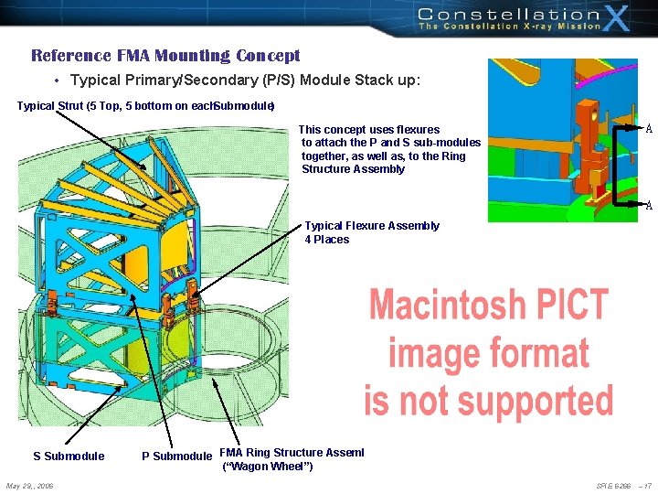
Reference FMA Mounting Concept • Typical Primary/Secondary (P/S) Module Stack up: Typical Strut (5 Top, 5 bottom on each. Submodule) A This concept uses flexures to attach the P and S sub-modules together, as well as, to the Ring Structure Assembly A Typical Flexure Assembly 4 Places S Submodule May 29, , 2006 P Submodule FMA Ring Structure Assembly (“Wagon Wheel”) SPIE 6266 – 17
OAP 2 unit for mirror pair alignment and mounting demonstration Retroreflector Actuator plate (1 of 4) ~95 percent of each mirror surface is viewable by instrumentation at normal incidence Mirror surfaces Cylindrical null lens assembly Fully assembled OAP 2 unit in alignmentfaclity May 29, , 2006 SPIE 6266 – 18
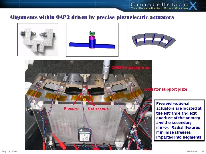
Alignments within OAP 2 driven by precise piezoelectric actuators CMM Contact probe Actuator support plate Flexure May 29, , 2006 Set screws Five bidirectional actuators are located at the entrance and exit aperture of the primary and the secondary mirror. Radial flexures minimize stresses imparted into segments SPIE 6266 – 19
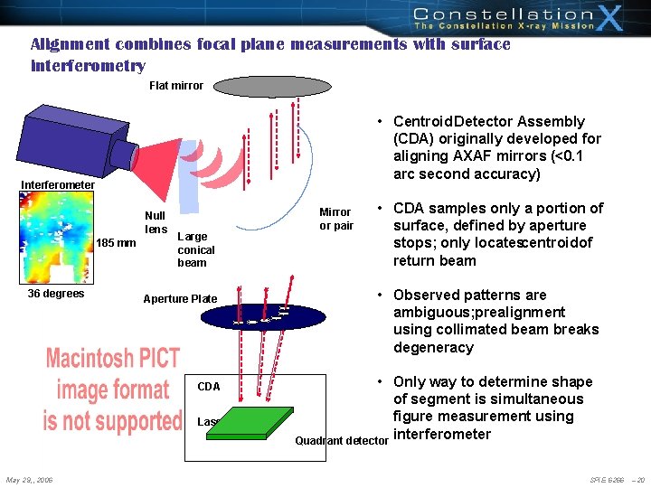
Alignment combines focal plane measurements with surface interferometry Flat mirror • Centroid Detector Assembly (CDA) originally developed for aligning AXAF mirrors (<0. 1 arc second accuracy) Interferometer Null lens 185 mm 36 degrees Large conical beam Aperture Plate CDA Laser May 29, , 2006 Mirror or pair • CDA samples only a portion of surface, defined by aperture stops; only locatescentroid of return beam • Observed patterns are ambiguous; prealignment using collimated beam breaks degeneracy • Only way to determine shape of segment is simultaneous figure measurement using interferometer Quadrant detector SPIE 6266 – 20
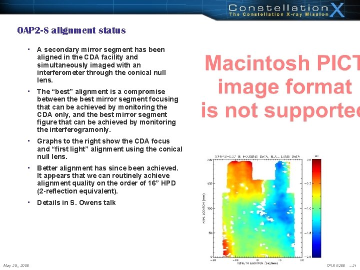
OAP 2 -S alignment status • A secondary mirror segment has been aligned in the CDA facility and simultaneously imaged with an interferometer through the conical null lens. • The “best” alignment is a compromise between the best mirror segment focusing that can be achieved by monitoring the CDA only, and the best mirror segment figure that can be achieved by monitoring the interferogramonly. • Graphs to the right show the CDA focus and “first light” alignment using the conical null lens. • Better alignment has since been achieved. It appears that we can routinely achieve alignment quality on the order of 16” HPD (2 -reflection equivalent). • Details in S. Owens talk May 29, , 2006 SPIE 6266 – 21
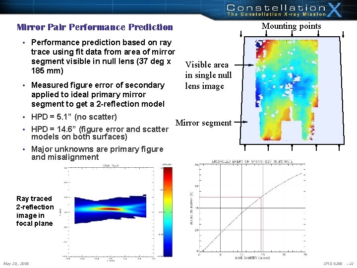
Mounting points Mirror Pair Performance Prediction • Performance prediction based on ray trace using fit data from area of mirror segment visible in null lens (37 deg x 185 mm) • Measured figure error of secondary applied to ideal primary mirror segment to get a 2 -reflection model • HPD = 5. 1” (no scatter) • HPD = 14. 6” (figure error and scatter models on both surfaces) Visible area in single null lens image Mirror segment • Major unknowns are primary figure and misalignment Ray traced 2 -reflection image in focal plane May 29, , 2006 SPIE 6266 – 22
Plans for Coming Year (and Beyond) • Mount and align one or more pairs of mirror segments – Perform in situ full surface metrology within OAP 2 mount – Demonstrate that aligned segments meet the Constellation-X HPD requirement – Quantify residual errors to determine most significant contributions – Compare 3 D segment surface measurements and distortions (using special metrology mount) with optical and mechanical models • Verify performance of aligned mirror pair(s) in X-rays; compare with predictions from metrology • Continue development of alignment procedures – Introduce next generation. Piezo actuators – Integrate collimated beam, surface profileinterferometry, and CDA • Refigure forming mandrel pair to allow 3 arc second HPD (Con-X goal) • Procure and test 50 cm “slab” forming mandrel – Couple with thermo-mechanical modeling of forming process – Initiate conversion of forming to “flight-like” mandrels • Involve industry in studies of Flight Mirror Assembly and mandrel fabrication – Mandrel fabrication is critical path of the program - need to identify multiple suppliers – Mounting process could benefit from independent engineering study • New funding reductions will significantly delay all mirror technology development, and could result in irretrievable loss of knowledge May 29, , 2006 SPIE 6266 – 23
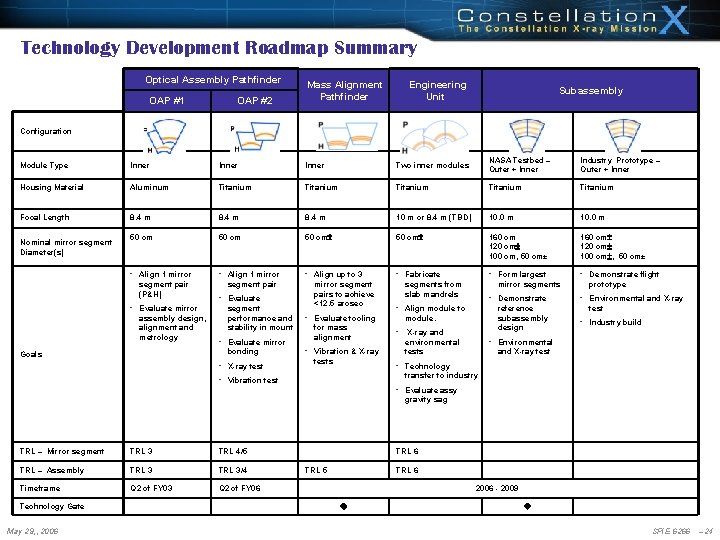
Technology Development Roadmap Summary Optical Assembly Pathfinder OAP #1 OAP #2 Mass Alignment Pathfinder Engineering Unit Subassembly Configuration Module Type Inner Two inner modules NASA Testbed – Outer + Inner Industry Prototype – Outer + Inner Housing Material Aluminum Titanium Titanium Focal Length 8. 4 m 10 m or 8. 4 m (TBD) 10. 0 m 50 cm 160 cm 120 cm 100 cm, 50 cm± 160 cm 120 cm 100 cm , 50 cm± • Align 1 mirror • Align up to 3 • Fabricate • Form largest • Demonstrate flight Nominal mirror segment Diameter(s) segment pair (P&H) • Evaluate mirror assembly design, alignment and metrology segment pair • Evaluate segment performance and stability in mount • Evaluate mirror bonding Goals • X-ray test mirror segment pairs to achieve <12. 5 arcsec • Evaluate tooling for mass alignment • Vibration & X-ray tests segments from slab mandrels mirror segments • Demonstrate • Align module to reference subassembly design module. • X-ray and prototype • Environmental and X-ray test • Industry build • Environmental environmental tests and X-ray test • Technology transfer to industry • Vibration test • Evaluate assy gravity sag TRL – Mirror segment TRL 3 TRL 4/5 TRL – Assembly TRL 3/4 Timeframe Q 2 of FY 03 Q 2 of FY 06 Technology Gate May 29, , 2006 TRL 5 TRL 6 2006 - 2009 SPIE 6266 – 24
Summary • Significant progress made in some areas of SXT mirror development despite substantial funding reduction – High quality substrates made reliably and faithfully reproduce mandrel surface – We understand the origin of many of the substrate errors and how to remove them – Substrate performance is limited by mandrel figure – Alignment principles have been demonstrated; we are close to having a segment pair aligned – Substantial evidence exists that mirrors have correct overall shape • Metrology uncertainties limit our knowledge of the segment quality – Two new tools (MMTC, high speed interferometer) coming on line to address these uncertainties – Mounting has been a crucial limitation of metrology – We have not yet measured the true 3 D shape of a segment • Strong coupling between mounting and alignment is becoming understood – See talk by Scott Owens • X-ray test using aligned segment pair should yield performance consistent with Con-X requirement – Supporting metrology data will ensure an accurate performance prediction May 29, , 2006 SPIE 6266 – 25