Si Solar Cell Kirsi Keronen 355825 Charlie Zhang


- Slides: 17

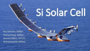
Si Solar Cell Kirsi Keronen, 355825 Charlie Zhang, 292821 Giovanni Marin, 337171 Muhammad Ali, 545442

How does it work? Front electrode (-) Antireflection coating N-type (P doped) P-type (B doped) Back electrode (+) Protective layer

Materials • Silicon (monocrystalline 3%, polycrystalline silicon) • Thin Films: Amorphous Si, Cadmium Telluride (Cd-Te), Copper Indium Gallium Selenide (Cu-In-Ga-Se) • Dopants: Boron (P-type), Phosphorous (N-type) • Titanium Dioxide, Silicon oxide and Aluminium oxide as anti-reflecting coating and passiavation • Support and protection: Glass 75%, steel and polymers • Contacts and Cables: Aluminium 10%, Silver, Copper, Zinc, etc.

State of art materials used • Black silicon SC • Thin film crystalline Si on glass

Comparison to Vesborg’s article • No mucho problemos!! • Uno problemo porfavore: silver • Inte so mycke problem, vi måste inte use that, vi kan use copper instäd

Erbium upconverter Improvement of 0, 19% S. Fischer, E. Favilla, M. Tonelli, and J. C. Goldschmidt, “Record efficient upconverter solar cell devices with optimized bifacial silicon solar cells and monocrystalline Ba. Y 2 F 8: 30% Er 3+ upconverter, ” Sol. Energy Mater. Sol. Cells, vol. 136, pp. 127– 134, May 2015

Black silicon solar cells with interdigitated back-contacts achieve 22, 1% efficiency Pic 1: Solar cells built with black silicon are much more lightabsorbent, and can capture incident photons from very low angles Result • B-Si property absorbing light with high acceptance angles -> the high efficiency can be maintained independently of the direction of the incoming light • Results show b-Si no longer limiting the cell efficiency -> further improvements possible by improving the cell structure • Efficiencies above 22% can be reached, even in thick interdigitated back-contacted cells, where carrier transport is very sensitive to front surface passivation Pic 2: A thin Al 2 O 3 layer is deposited on the nanostructured front surface Pic 3: a, SEM image of a b. Si surface. The 20 nm Al 2 O 3 is the brighter layer on top of the pillars. b, Reflectance spectra in the 300– 1, 000 nm wavelength range. The dashed line represents the reflectance of a bare b-Si sample and the black solid line shows the reflectance of b-Si with 20 nm of Al 2 O 3 Reference : Savin, H. Repo, P. Et al. Black silicon solar cells with interdigitated back-contacts achieve 22. 1% efficiency. Nature Nanotechnology, volume 10. Pages 624 -628. Published 18 May 2015. DOI: 10. 1038/nnano. 2015. 89

New efficient solar cell structures based on zinc oxide nanorods Why Zn. O nanorods? • Effective antireflection coating for cells • Deposit easily at low cost and in short time • Consider as good material for low cost solar cell technology Result • Zn. O nanorods grown on p- type silicon surface by hydrothermal method • Efficiency were different with Zn. O film thickness • Higher efficiency of 10. 9 % on 500 nm Zn. O film achieved Fig 1: Schematic diagram of the investigated solar cell structure Fig 2: Schematic diagram explaining the growth mechnism of Zn. O layer on nonorods in ALD growth chamber at 160 C and 1 mbar pressure Fig 3: High efficiency achieved on sample D of 10. 9% Reference : New efficient solar cell structures based on zinc oxide nanorods, R. Pietruszka, B. S. Witkowski, S. Gieraltowska, P. Caban, L. Wachnicki, E. Zielony, K. Gwozdz, P. Bieganski, E. Placzek-Popko, M. Godlewski, Solar energy Materials & Solar cells 143 (2015) 99 – 104

Graphenized Carbon Nanofiber Reference: X. Chen, B. Jia , B. Cai , J. Fang , Z. Chen , X. Zhang , Y. Zhao , and M. Gu, “Graphenized Carbon Nanofiber: A Novel Light. Trapping and Conductive Material to Achieve an Efficiency Breakthrough in Silicon Solar Cells” (2014). DOI: 10. 1002/adma. 201404123

Annealing at 250 °C. Ni. Si 2/Ni/Cu Ni. Si 2/Ni 71 Co 29/Cu Q. Huang, K. B. Reuter, Y. Zhu, and V. R. Deline, “A Study on the Long-Term Degradation of Crystalline Silicon Solar Cells Metallized with Cu Electroplating, ” ECS J. Solid State Sci. Technol. , vol. 5, no. 2, pp. Q 24–Q 34, Jan. 2016

Light-Induced degradation of Thin Film Silicon Solar Cells Thin Film Amorphous Silicon cell • Uses thin absorbing layer of few 100 nm resulting in • Lower material demand • Low production cost • But efficiency are low Problem • Light induced degradation (LID) result in lower efficiency • During LID weak silicon-hydrogen bond breaks and density of defects increases • LID depends on following parameters, quality of a. Si layer, thickness , temperature, light intensity Fig 1: Degradation of a-Si cells with different i-layer thickness Result • LID can be minimized by choosing right substrate, layer thickness • But decresing LID has disadvantage also like more raw material used, lower depostion rate and lower production output Fig 2: Efficiency of cells with different i-layer thickness during LID Reference: Light-Induced degradation of Thin Film Silicon Solar Cells, F U Hamelmann, J A Weicht and G Behrens, Journal of Physics, 682 (2016) 012002

Potential-induced degradation in photovoltaic modules based on n-type single crystalline Si solar cells • Result N-type • Surface polarization effect decreased the PV performance of a high efficiency n-type BC Si solar cell by applying high positive voltage to the Si cell • Degradation mechanism of PV modules by high voltage stress significantly depends on the structure and type of Si cell • PID easily occurred in n-type single crystalline Si PV modules, compared to p-type multicrystalline P-type • • PID can be basically avoided by using Na-free front cover substrates PID can be significantly suppressed by using a acrylic-film as a front cover substrate Fig 1: The spectra of external quantum efficiency for a standard n -type FJ Si PV module (a) before and (b) after PID test (− 1000 V at 85 °C for 2 h). Reference: Hara, K. Jonai, S. Masuda, A. Potential-induced degradation in photovoltaic modules based on n-type single crystalline Si solar cells. Solar Energy Materials and Solar cells. Volume 140, September 2015, Pages 361 -365.

Backsheets as protection Fig. 1. Illustrated incident light into the PV module and its reflection (schematic of cross-section of silicon photovoltaic module). Reference: N. Kim, S. Lee, X. G. Zhao, D. Kim, C. Oh, H. Kang, “Reflection and durability study of different types of backsheets and their impact on c-Si PV module performance” (2015). http: //dx. doi. org/10. 1016/j. solmat. 2015. 11. 038

Recycling of Si solar cells Charlie Zhang, Giovanni Marin, Muhammad Ali, Kirsi Keronen

Dong, A. ; Zhang, L. ; Damoah, L. ; “Beneficial and technological analysis for the recycling of solar grade silicon wastes”; JOM. 2011, 63, 23.

GHG emission of PV solar cells PV manufacturing >88% (37% Si) Operation <0. 1% Decommissioning 10% Energy requirement of PV PV manufacturing >88% (38% Si) Operation <0. 2% Decommissioning 11% Review of life cycle analyses and embodied energy requirements of single-crystalline and multi-crystalline silicon photovoltaic systems, J. h. Wong, M. Royapoor, C. W. Chan, Renewable and sustainable energy reviews 58 (2016) 608618

Indium • Limited production – Depended on the Zn production (by-product) – Not possible to adjust the production to the demand – Material lost if not extracted in the mine • No In is recycled at the moment • Used in small quantities in electronics • 580 t used in 2011, only 1% recovered • If In from ITO was recycled -> 380 t recovered up to 440 t if the deposition tech was 70% efficient
 Kirsti keronen
 Kirsi sipiläinen
 Kirsi alila
 Kirsi rojo-hellström
 Kirsi levä
 Kirsi kostia
 Castrn
 Kirsi heino
 Poliisi amk
 Kirsi heino
 Kirsi heino
 Paikasta riippumaton työ
 Wholesale solar
 Inexhaustible source of energy
 What is fill factor of solar cell
 Difference between solar cell and photodiode
 Solar cell vi characteristics
 Solar cell iv
