Registers Reference Chapter 7 Moris Mano 4 th

- Slides: 18
Registers Reference Chapter 7 Moris Mano 4 th Edition
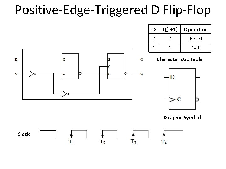
Positive-Edge-Triggered D Flip-Flop D Q(t+1) Operation 0 0 Reset 1 1 Set Characteristic Table Graphic Symbol Clock
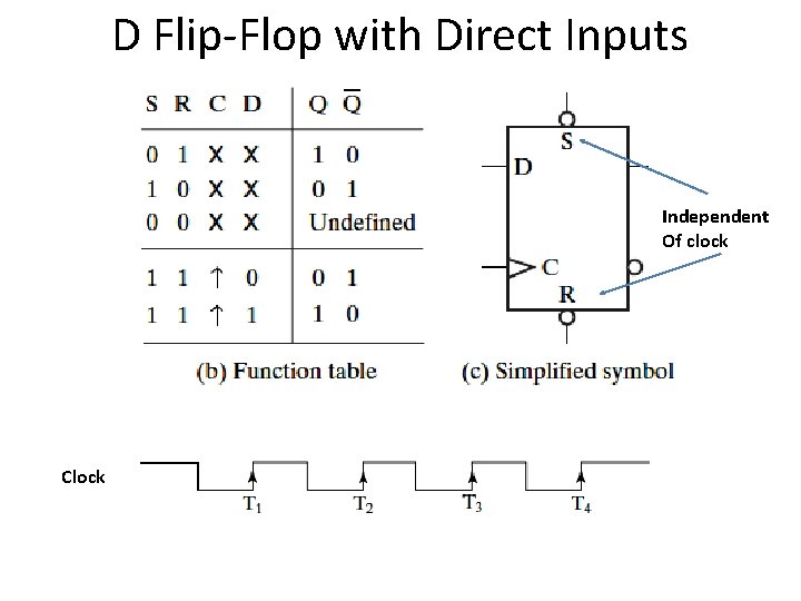
D Flip-Flop with Direct Inputs Independent Of clock Clock
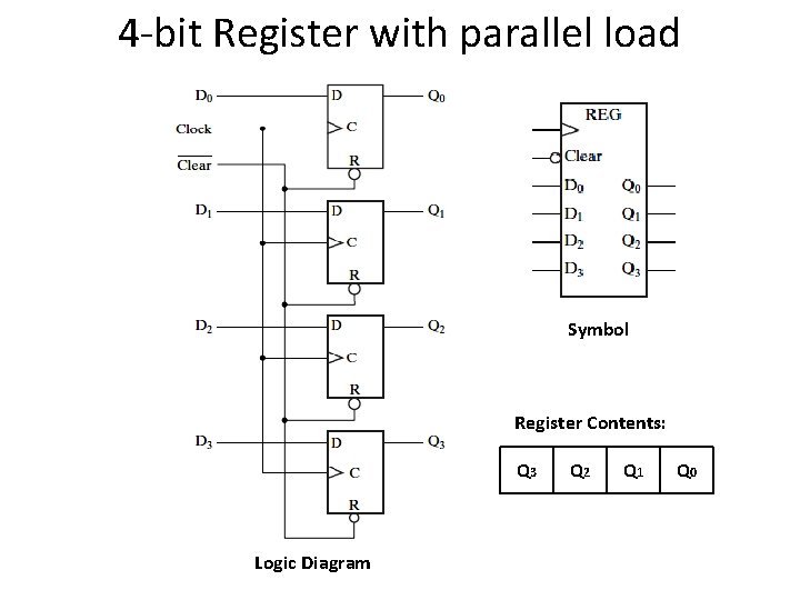
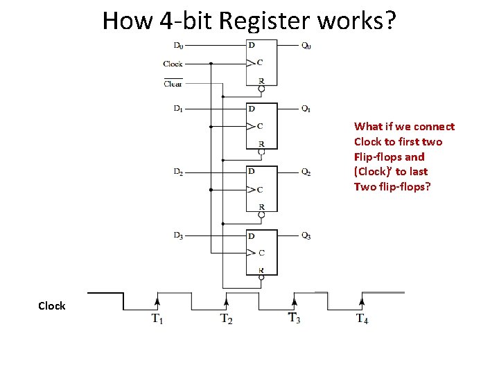
4 -bit Register with parallel load Symbol Register Contents: Q 3 Logic Diagram Q 2 Q 1 Q 0
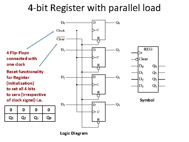
4 -bit Register with parallel load 4 Flip-Flops connected with one clock Reset functionality for Register (initialization) to set all 4 bits to zero (irrespective of clock signal) i. e. Symbol 0 0 Q 3 Q 2 Q 1 Q 0 Logic Diagram
How 4 -bit Register works? What if we connect Clock to first two Flip-flops and (Clock)’ to last Two flip-flops? Clock
Register Load: “Transfer of new information into a register” Parallel Loading: All the bits of register loaded simultaneously with a common clock pulse
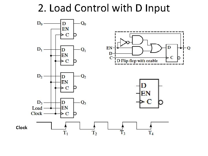
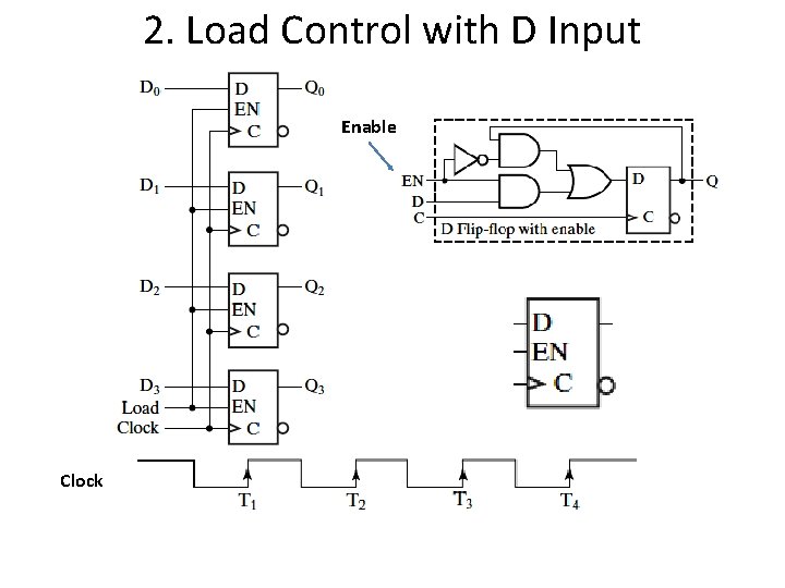
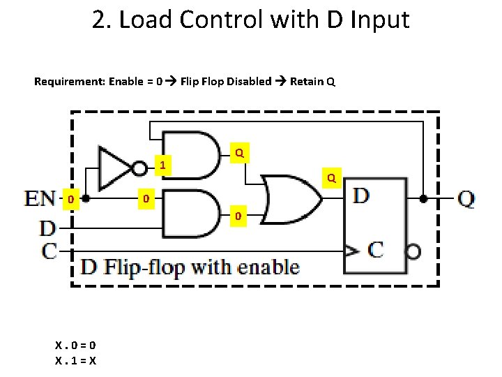
Register Load Problem: Keep the data saved until user wants to change it i. e. Do not update contents with clock. Solution: Update register functionality such that: Load = 0 Content unchanged even with clock Load = 1 Follow the clock to change the contents
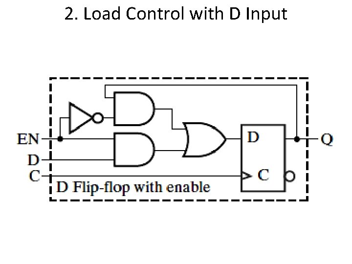
Register Load Methods to control Register Load: 1. Load control with Clock Gating: Prevent clock from reaching the flipflops 2. Load control with D Input
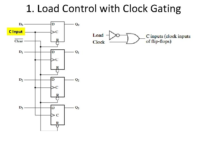
1. Load Control with Clock Gating C Input
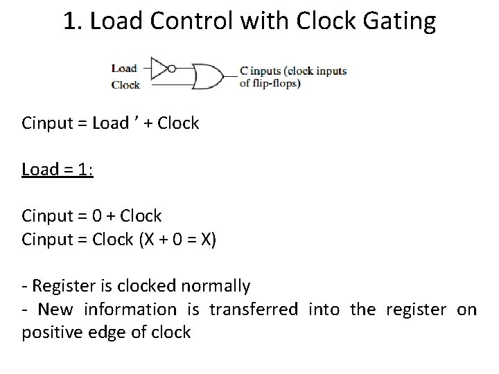
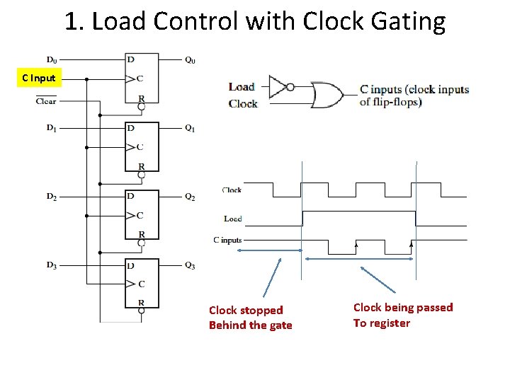
1. Load Control with Clock Gating Cinput = Load ’ + Clock Load = 1: Cinput = 0 + Clock Cinput = Clock (X + 0 = X) - Register is clocked normally - New information is transferred into the register on positive edge of clock
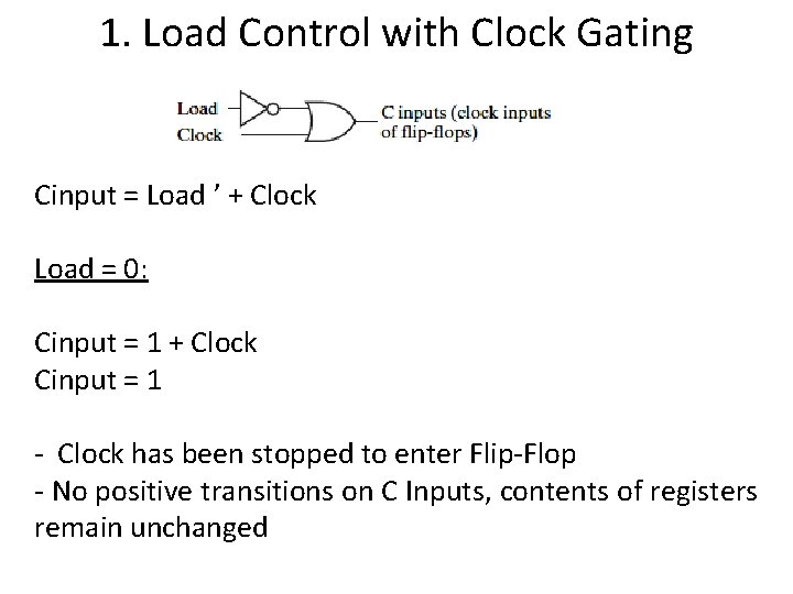
1. Load Control with Clock Gating Cinput = Load ’ + Clock Load = 0: Cinput = 1 + Clock Cinput = 1 - Clock has been stopped to enter Flip-Flop - No positive transitions on C Inputs, contents of registers remain unchanged
1. Load Control with Clock Gating C Input Clock stopped Behind the gate Clock being passed To register
2. Load Control with D Input Clock
2. Load Control with D Input Enable Clock
2. Load Control with D Input
2. Load Control with D Input Requirement: Enable = 0 Flip Flop Disabled Retain Q 1 0 Q Q 0 0 X. 0=0 X. 1=X
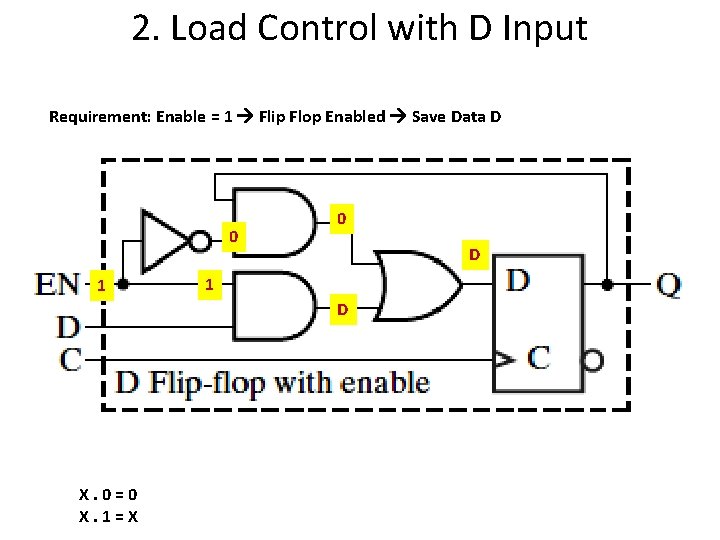
2. Load Control with D Input Requirement: Enable = 1 Flip Flop Enabled Save Data D 0 1 0 D 1 D X. 0=0 X. 1=X