RBE 595 Space and Planetary Robotics Lecture 4

RBE 595: Space and Planetary Robotics Lecture 4 Professor Marko B Popovic A term 2019

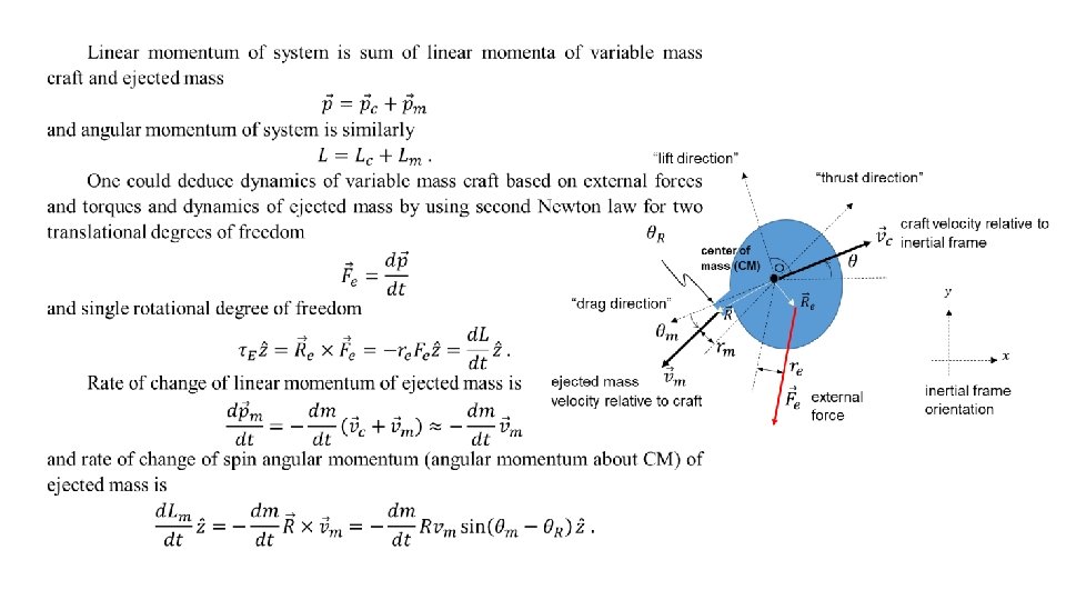
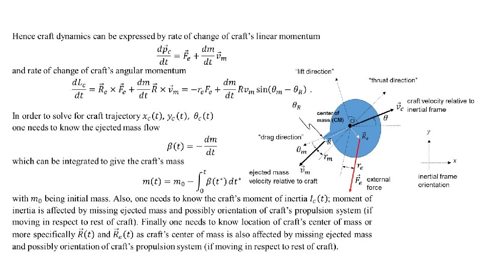
Dynamics: 2 D modeling “lift direction” “thrust direction” craft velocity relative to inertial frame center of mass (CM) “drag direction” ejected mass velocity relative to craft external force inertial frame orientation Terms “lift direction”, “drag direction”, and “thrust direction” are frequently used in literature however often without being properly introduced.
")
“lift direction” “thrust direction” craft velocity relative to inertial frame center of mass (CM) “drag direction” ejected mass velocity relative to craft external force inertial frame orientation
")
“lift direction” “thrust direction” craft velocity relative to inertial frame center of mass (CM) “drag direction” ejected mass velocity relative to craft external force inertial frame orientation
")
“lift direction” “thrust direction” craft velocity relative to inertial frame center of mass (CM) “drag direction” ejected mass velocity relative to craft external force inertial frame orientation

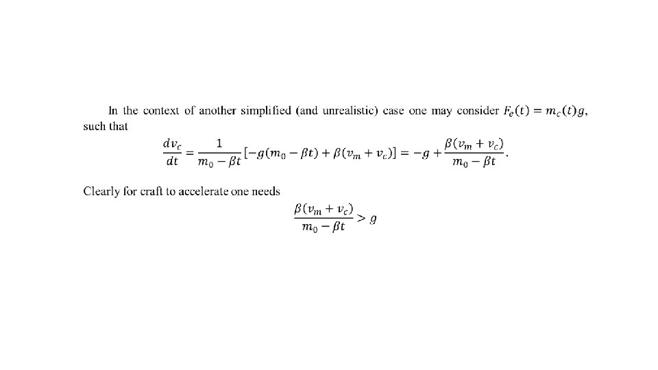
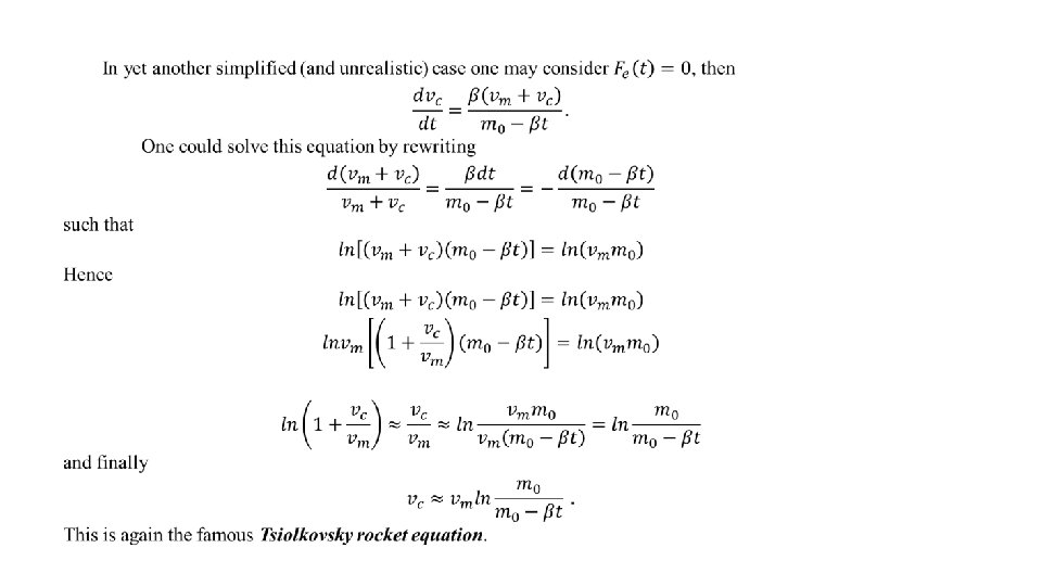
From 2 D to 1 D dynamics modelling

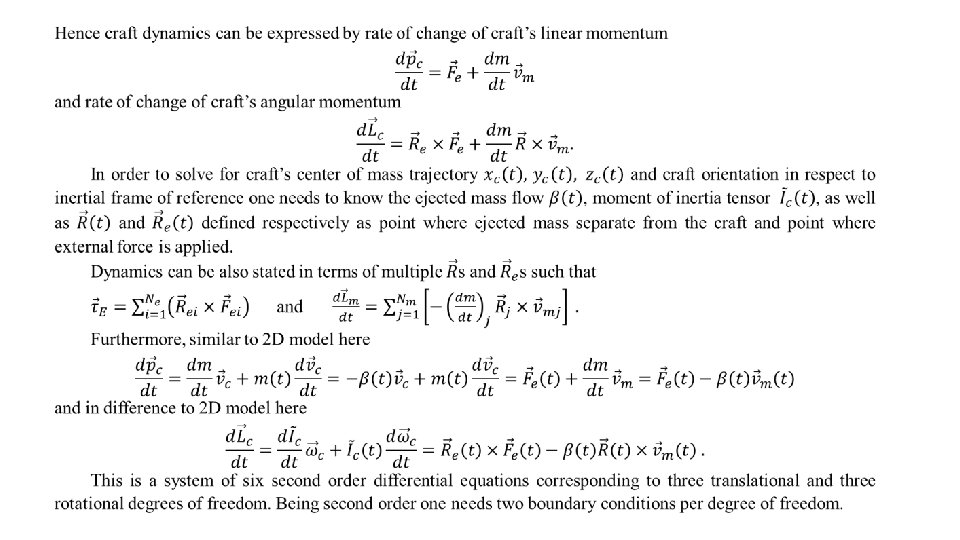
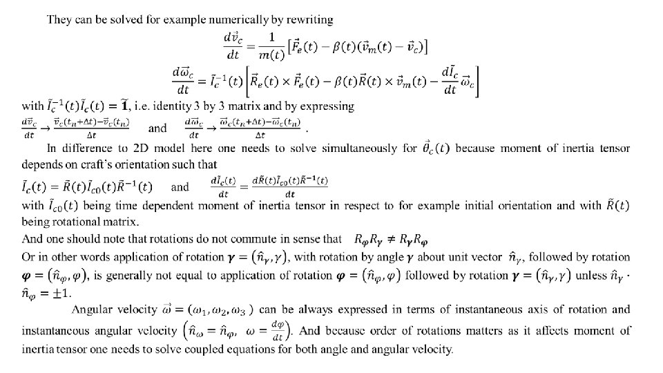
Dynamics: 3 D modelling

A few hints for Homework 1 We need here 2 component force and 1 component torque (that is moment of force)
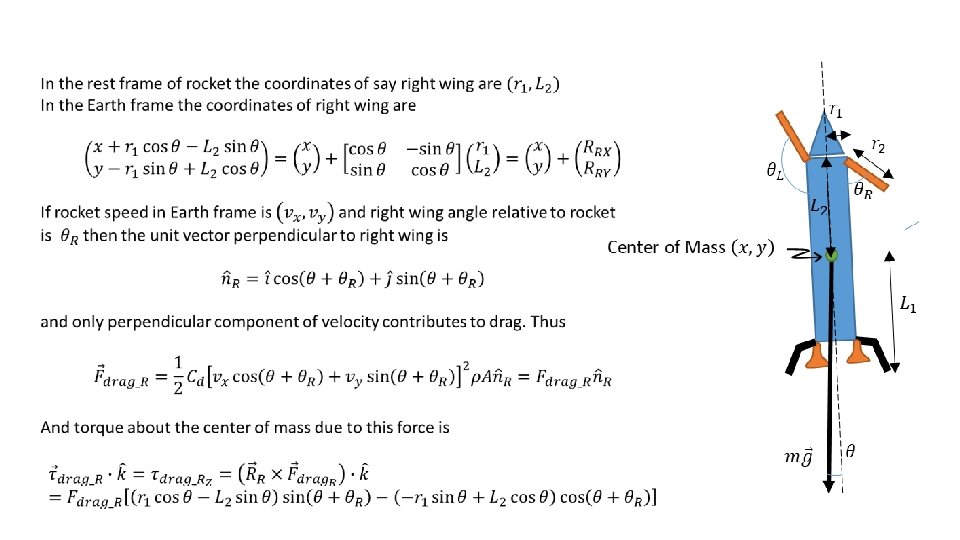
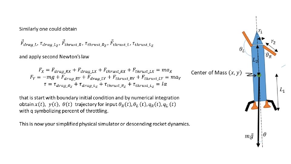

In this problem you have 4 control variables for only 3 controlled degrees of freedom. If you try to minimize the amount of fuel you burn then is essence you are introducing weighting factor on you input control variables. One way to think about this problem is to realize that drag forces are quite large when speed is large. So maybe you want to exploit that feature as much as possible at beginning of descent and then switch fully to thrusters when speed substantially drops. (some numbers: at beginning max drag forces can be ~48 k. N compared to maximal ~56 k. N from thrusters) You may use PID type of controller. You probably don’t need I part but just P and D. It is unlikely that you could get away with only P part as you need to minimize the impact speed too. But you may try.

PID control where desired position may be time dependent and may not be known in advance (i. e. one should not assume knowledge of future desired trajectory). Here we used position, but in principle one could use any other physical or abstract quantity.
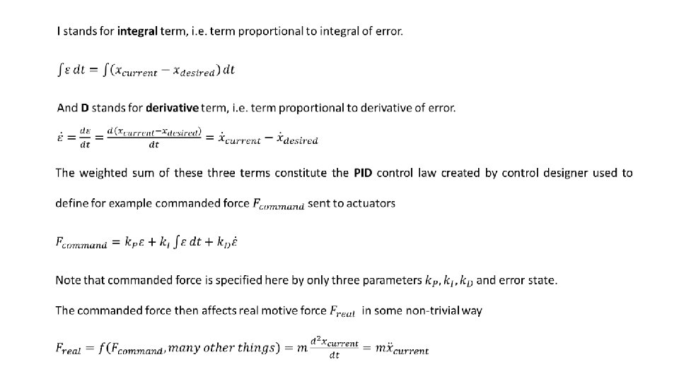

Quite generally the role of the three terms P, I, and D, depends on the details of the actual physical system. Control designer fine tunes these parameters by trial and error method. Experienced control designer typically quickly recognizes the type of physical dynamics and relative importance of terms. In the PID “kitchen” the P term typically plays the role of a spring that drives the current position towards an equilibrium position related to the desired position and likely cause oscillations about that equilibrium point. The D term typically plays the role of damping that may decrease the amplitude or completely remove these oscillations. The I term plays a role like P, but has a ‘memory’ of previous errors though integration, and it is typically used to regulate the steady state error; one just needs to make sure that there is not much overshoot and that the solution is stable. In most practical cases only two terms (PD, PI, or ID) are sufficient to provide working though non-optimal solution.
- Slides: 22